|
|
|
Who's Online
There currently are 5985 guests online. |
|
Categories
|
|
Information
|
|
Featured Product
|
|
|
 |
|
|
There are currently no product reviews.
 ;
good and ok, very nice , good and ok, very nice, good and ok, very nice
;
Super manual it contains all the things you need to service your Marantz 2100.
;
A very easy to understand and use manual. Well worth the money.
 ;
Very good information with clear drawings. Thanks!
;
The ease of this purchase was a good start. The content of this manual was exactly all I needed to retore my Tandberg 64.
All of the mechanical and electrical information is contained in the manual and the quality of the document makes reading the data easy.
The exerience with the resource has made this my prime source for technical data.
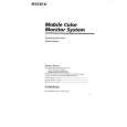
SECTION 2 ELECTRICAL ADJUSTMENTS
Equipment Use the following test equipment for alignment. � Oscilloscope dual trace, 10 MHz band or above with delay mode (use a 10 to 1 probe unless otherwise instructed.) � NTSC color bar generator � PAL color bar generator � DC power supply � Digital voltmeter � XT-61VE (TV tuner unit of XTL-610E) (XVM-61EX only) � Frequency counter Equipment Connections Make the test equipment connections as shown below (unless instructed otherwise) and perform the alignment. XVM-61EX :
NAVI INPUT (VIDEO) XT-61VE XVM-611EX
MONITOR SECTION
Voltage Adjustment Setting : DIMMER selector (S701) : HIGH BRIGHT dial (RV702) : Max. (light) VOL dial (RV301) : Max. Procedure : 1. Input the color bar (chroma off) signal from NTSC color bar generator and display on the monitor screen. 2. Connect the digital voltmeter to CL66 on the monitor main board. 3. Adjust RV401 (+5V) so that the digital voltmeter reads 5±0.1 V DC. 4. Connect the digital voltmeter to CL86 on the monitor main board. 5. Adjust RV601 (+9V) so that the digital voltmeter reads 8.5±0.1 V DC. Connection points : Monitor main board Refer to page 5. Alignment points : Monitor main board Refer to page 5. RGB Adjustment Procedure : 1. Input the color bar (chroma off) signal from NTSC color bar generator and display on the monitor screen. 2. Connect the digital voltmeter to CL151 on the monitor main board. 3. Adjust RV213 (OFFSET) so that the digital voltmeter reads 2.3±0.1 V DC. 4. Connect the oscilloscope to CL42 on the monitor main board. 5. Adjust RV212 (COM CUT) so that the lower black level is 6.2±0.05 V DC. 6. Adjust RV208 (COM DRIVE) so that the upper 100% white level is 9.2±0.05 V DC. 7. Repeat steps 5 & 6 until the items in the standards are satisfied. 8. Connect the oscilloscope to CL41 of the monitor main board. 9. Adjust RV207 (R DRIVE) so that the lower black level is 6.2±0.05 V DC. 10. Adjust RV202 (R CUT) so that the upper 100% white level is 9.2±0.05 V DC. 11. Repeat steps 9 & 10 until the items in the standards are satisfied. 12. Connect the oscilloscope to CL43 of the monitor main board. 13. Adjust RV209 (B DRIVE) so that the upper 100% white level is 6.1±0.05 V DC. 14. Adjust RV204 (B CUT) so that the upper 100% white level is 9.1±0.05 V DC. 15. Repeat steps 13 & 14 until the items in the standards are satisfied.
1 2 3 5 6 7 8 black level (8th step) 0V 4
color bar generator
VIDEO output (75 �)
MONITOR OUTPUT
XVM-6100 :
INPUT 1 (VIDEO) XA-601
color bar generator
MONITOR OUTPUT XVM-611
CONTROLLER VIDEO output (75 �) RM-X6100
white level (1st step)
Connection points : Monitor main board Refer to page 5. Alignment points : Monitor main board Refer to page 5.
�4�
|
|
|
> |
|