A site where discontinualed schematic diagrams and back dated information can be found on discontinued radios tv's and any electronic equipment can be found. Newer manuals either Service and operating manuals. Radio amateurs should find this site a great source for ham radio equipment manuals. I will return to this site should I need information on any electrical equipment. priced easy to download in a PDF format and print pages need to undertake the repair.
Quality scan of the original. All the detail necessary to troubleshoot, repair and adjust the unit. I'm sure I will be downloading more manuals in the future as the need arises.
Well.. I'd searched for this manual and although I found many copies online I was pleased to find your website with a well balanced pricing system and easy to search and follow links. That together with the very quick response time was just what I was looking for.. being a very impatient tech.. ;-) I had the service manual in front of me within a short time.
Bookmarked.. and you can bet I will always come here first for my service & user manuals..
best regards
Ed(Tony) Foley
G7WHK
Text excerpt from page 3 (click to view)
SECTION 1 SERVICE NOTE
Clearing the Protector During Repairs
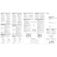
� OVER CURRENT : Detects overcurrent during output. � OFF SET : Detects DC offset at the speaker terminal. 1. Clearing the OVER CURRENT protector 1 When the position of the MODE switch (S801/power board) is set to HI-VOLTAGE : Cut the jumper wire JW065 of the amplifier board. 2 When the position of the MODE switch (S801/power board) is set to HI-CURRENT : Cut the jumper wire JW066 of the amplifier board. 2. Clearing the OFF SET protector � Cut the jumper wire JW024 of the amplifier board. 3. TEST TONE Function 1 Press the TEST TONE button (S805/amplifier board) with the power ON. The amplifier is normal if sound is produced from the speaker. 2 If no sound : Problem causer by incorrect connecttion of the power supply system or sperker system. : The signals input by the RCA cable before the amplifier system are abnormal. Adjustment Location: - POWER BOARD - (Component side)
S801 MODE
- AMPLIFIER BOARD - (Component side)
S805 VR201 JW024 JW065 JW066 VR101 TEST TONE