|
|
|
Who's Online
There currently are 6043 guests online. |
|
Categories
|
|
Information
|
|
Featured Product
|
|
|
 |
|
|
There are currently no product reviews.
 ;
Excellent printing quality.
A complete and very usefull service manual with all details.
GREAT SERVICE AT VERY LOW PRICE!
A+++++++++++++++++++++++++
;
Pioneer CDXP23S is an old model and has been top useful for me to find this Manual. CD Player is still repaired.
;
Inventory (Stock): a rather extensive list of service manuals, which are hard to find, especially 15+ yrs old.
Pricing: very reasonable.
Delivery/Response: Very Prompt delivery of product: Placed order and received download access within 1.5hrs.
Service Manual: a rather complete OEM service manual (15.5MB pdf file size). Scan quality was very good, accept for a few circuit board diagrams that were dark; Zooming, however, clarified the image. Has the required information for servicing the LD Player.
;
Perfect copy of a necessary document and my Sonic Modulator is repaired!
;
Excellent replacement for original Manual. Worth every cent ! I am totally satisfied!
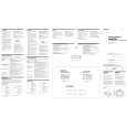
XM-280GTX SECTION 3 DIAGRAMS
2-4. MAIN BOARD
THIS NOTE IS COMMON FOR PRINTED WIRING BOARDS AND SCHEMATIC DIAGRAMS. (In addition to this, the necessary note is printed in each block.) for schematic diagram: Note: � All capacitors are in µF unless otherwise noted. pF: µµF 50 WV or less are not indicated except for electrolytics and tantalums. � All resistors are in � and 1/4 W or less unless otherwise � � � � � � � specified. % : indicates tolerance. 2 : nonflammable resistor. A : B+ Line. B : B� Line. Power voltage is dc 14.4V and fed with regulated dc power supply from +12V and REM terminals. Voltage is dc with respect to ground under no-signal condition. Voltages are taken with a VOM (Input impedance 10 M�). Voltage variations may be noted due to normal production tolerances. Waveforms are taken with a oscilloscope. Voltage variations may be noted due to normal production tolerances.
3 P 3x8
�
5 MAIN board 2 P 3x8
� Circled numbers refer to waveforms. � Signal path. F : AUDIO
1 P 3x8 4 panel (front)
for printed wiring boards: Note: � X : parts extracted from the component side. � : Pattern from the side which enables seeing. (The other layer�s patterns are not indicated.) Caution: Pattern face side: Parts on the pattern face side seen from the (Side B) pattern face are indicated. Parts face side: Parts on the parts face side seen from the (Side A) parts face are indicated.
2-5. LED BOARD
1 P 3x6
3-1. IC BLOCK DIAGRAM
2 LED board
IC8 TL494CN
OUT VCC C2
11 16 15 14 13 12 REF 5V 10
E2
9 6 78
heat sink (main)
ERROR
ERROR 1 2 3
0.1V
OSC
4
5
-IN INV
TIME
� Waveform
1
1V/DIV, 5µsec/DIV 3.4Vp-p 15µsec
COMP EN VREF
IC8
5
9
9
GND C1 E1
+IN NON
RT
CT
|
|
|
> |
|