|
|
|
Who's Online
There currently are 5984 guests online. |
|
Categories
|
|
Information
|
|
Featured Product
|
|
|
 |
|
|
There are currently no product reviews.
 ;
muy buen manual por lo completo de este algunos esquemas estan muy divididos lo que hace algo dificil el seguimiento.
;
very good manual, with detail and clarity in esquematic diagrams and waveforms .
 ;
Very quality copy of original service manual, which contains the circuit diagrams, PCB and lists of components, well as recommendation for calibration procedures of device, also everything else, that need for repair, tuning and use this oscilloscope.
All presented copies have high-resolution, so you can view all in detail.
This manual will very useful for simple owners and for repairers.
I recommend these manual, because myself is owner of Philips PM3216 and I need sometimes servicing these oscilloscope (principally calibrating).
Also, these document is an example of excellent design of technical documentation.
;
Excellent printing quality.
A complete and very usefull service manual with all details.
GREAT SERVICE AT VERY LOW PRICE!
A+++++++++++++++++++++++++
;
manual excelente completo , diagramas y esquemas bien presentados y buena calidad de imagen.
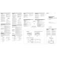
XM-2150GSX SECTION 3 ELECTRICAL ADJUSTMENT
Bias Adjustment
Note : In Bias Adjustment, adjust RV105 if any of Q108 through Q113 are replaced. Adjust RV205 if any of Q208 through Q213 are replaced. Condition : This adjustment should be performed about one minute after the remote mode is turned on at a room temperature of about 25°C. Setting :
B+, REM terminal
set Stabilized Power supply GND terminal
Procedure : 1. Turn the variable resistors RV105 (L-CH) and RV205 (R-CH) full clockwise as seen from the component side to minimize the bias current. 2. The input signal is to be no signal. 3. Apply the voltage to the B+ and REM terminals from the stabilized power supply and gradually increase it up to 14.4 V while checking for any unusual current. 4. Adjust each of RV105 (L-CH) and RV205 (R-CH) so that the power current of the stabilized power supply is increased in steps of 500 mA (total of 1 A). 5. After adjustment, check that the power current is at 1.3 to 2.0 A.
Adjustment Location : Main board (component side)
� MAIN BOARD (COMPONENT SIDE) �
RV105 BIAS ADJUSTMENT (L-CH)
RV205 BIAS ADJUSTMENT (R-CH)
8
|
|
|
> |
|