|
|
|
Who's Online
There currently are 5971 guests online. |
|
Categories
|
|
Information
|
|
Featured Product
|
|
|
 |
|
|
There are currently no product reviews.
 ;
The AKAI 1720 model reel to reel tape recorder described in this Manual is quite an old unit - circa late 1960's. As a consequence, the description of the mechanical details - and adjustments thereof - is quite critical. The manual does this quite well. The schematics are also well presented and have detailed PCB overlays. Probably the only negative is that some half-tone detail has been lost from the original manual as it has been scanned in simple B&W.
 ;
Perfect source for service manuals: fast and professional transaction; high quality, perfect readable and largely scaleable PDF; complete schemes, diagrams and spare part list. Tnx a lot, cu again!!!!
;
I got your link from a friend and I must say that I am really satisfied with your service. Specially this B&O manual I didn't find anywhere on the web... but you could deliver it :-) . You deliver very fast and the copy is of good quality. So your webpage is bookmarked. Thanks
;
This was the Sony CCU-500A Service manual I was looking for.
The price was reasonable.
The permission to download was quck.
I will use Owner-Manual.com for all my manual needs.
;
Excellent printing quality.
A complete and very usefull service manual with all details.
GREAT SERVICE AT VERY LOW PRICE!
A+++++++++++++++++++++++++
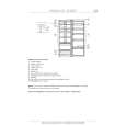
SECTION 3 ELECTRICAL ADJUSTMENT
Bias Adjustment
Note : The Bias adjustment should be performed only if any of Q108 to Q113 and Q208 to Q213 are replaced. Setting :
B+,REM terminal
set Stabilized Power suppy GND terminal
Procedure : 1. Rotate the variable resistors RV105 and RV205 fully in the clockwise direction to minimize the idling current of the stabilized power supply. 2. The input signal is to be no signal. 3. Set the power voltage to +14.4 V, and turn the remote mode ON (Connect between the REM terminal and B+ terminal). 4. Adjust each of RV105 and RV205 so that the power current of the stabilized power supply is increased in steps of 500 mA for the XM-1502SX and in steps of 600 mA for the XM-1902GX. Adjustment Location : Main board (component side)
� MAIN BOARD (COMPONENT SIDE) �
RV105 BIAS ADJUSTMENT
RV205 BIAS ADJUSTMENT
8
|
|
|
> |
|