|
|
|
Who's Online
There currently are 5793 guests online. |
|
Categories
|
|
Information
|
|
Featured Product
|
|
|
 |
|
|
There are currently no product reviews.
 ;
OEM manual provided all schematics, board layouts and component specs necessary to facilitate unit maintenance. All pages were clear and readable.
;
Good condition and quality. Hard to find anywhere in Internet, only on this site.
 ;
Exactly what I needed to be able to bring the amp back to life... will come back to this site the next time I need schematics.
;
Information was accurate and very helpful.
However the continuity made it a little difficult to follow from one page to the next.
;
Very very good as usual very trustable site. Perfect!!!!!!
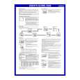
XM-1004GX SECTION 3 ELECTRICAL ADJUSTMENT
Bias Adjustment
Note : The Bias adjustment should be performed only if any of Q108 and Q110 for VR101, Q208 and Q210 for VR201, Q308 and Q310 for VR301, and Q408 and Q410 for VR401 are replaced. Setting :
Stabilized Power supply Digital Voltmeter
Adjustment Location :
� AMP BOARD (COMPONENT SIDE) � VR201 BIAS ADJUSTMENT (FRONT R-CH) VR301 BIAS ADJUSTMENT (REAR L-CH)
B+,REM terminals
set
+ _
VR101 BIAS ADJUSTMENT (FRONT L-CH)
VR401 BIAS ADJUSTMENT (REAR R-CH)
GND terminal
test points
Test Point Location : Procedure: 1. Rotate variable resistors VR101 (FRONT L-CH), VR201 (FRONT R-CH), VR301 (REAR L-CH) and VR401 (REAR RCH) full counterclockwise as seen from the pattern side to minimize the bias current. 2. The input signal is with no signal. 3. Connect the stabilized power supply between B+ and REM terminals and gradually increase the voltage to 14.4 V while checking for any abnormal current. 4. Adjust VR101 (FRONT L-CH), VR201 (FRONT R-CH), VR301 (REAR L-CH) and VR401 (REAR R-CH) so that the digital voltmeter connected between the respective test points reads 4.5±1 mV. RV Ref. No. VR101 VR201 VR301 VR401 Test points TP101 and TP102 TP201 and TP202 TP301 and TP302 TP401 and TP402
� AMP BOARD (CONDUCTOR SIDE) �
TP302 TP301
TP201 TP202
TP402 TP401
TP101 TP102
8
|
|
|
> |
|