|
|
|
Who's Online
There currently are 5865 guests and
3 members online. |
|
Categories
|
|
Information
|
|
Featured Product
|
|
|
 |
|
|
There are currently no product reviews.
 ;
The AKAI 1720 model reel to reel tape recorder described in this Manual is quite an old unit - circa late 1960's. As a consequence, the description of the mechanical details - and adjustments thereof - is quite critical. The manual does this quite well. The schematics are also well presented and have detailed PCB overlays. Probably the only negative is that some half-tone detail has been lost from the original manual as it has been scanned in simple B&W.
 ;
Perfect source for service manuals: fast and professional transaction; high quality, perfect readable and largely scaleable PDF; complete schemes, diagrams and spare part list. Tnx a lot, cu again!!!!
;
I got your link from a friend and I must say that I am really satisfied with your service. Specially this B&O manual I didn't find anywhere on the web... but you could deliver it :-) . You deliver very fast and the copy is of good quality. So your webpage is bookmarked. Thanks
;
This was the Sony CCU-500A Service manual I was looking for.
The price was reasonable.
The permission to download was quck.
I will use Owner-Manual.com for all my manual needs.
;
Excellent printing quality.
A complete and very usefull service manual with all details.
GREAT SERVICE AT VERY LOW PRICE!
A+++++++++++++++++++++++++
SECTION 1 SERVICING NOTES
This set detects the rotation of GEAR (PH) using the PH701 (photo reflector). The PH701 is mounted on the MAIN board, and therefore the GEAR cannot be detected with the MAIN board removed. As a result, the motor cannot be controlled, causing malfunction. Further, the S702 (FWD/REV switch) is also mounted on the MAIN board, and with the board removed, the mechanism position cannnot be detected and the operation is not changed over. Therefore, when the voltage check is executed with the MAIN board removed, follow the procedure provided below.
Note : Do not move the S702 swithc position when removing the MAIN board. If it is moved, the set will not be changed over to the selected mode. In this case, reconnect the MAIN board to the set and retry the work from the beginning.
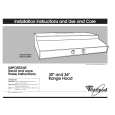
1. Setting 1) Refer to �3. DISASSEMBLY�, and remove the cabinet and open the MAIN board. 2) Connect the MAIN board to the M901 (motor) and PM901 (plunger) using jumper wires. 3) Short the ATS terminals. 4) Press and fixed the S701 (CASSETTE HOLDER). 5) Supply 1.5V to the battery terminals � and � using a stabilized power supply. 2. FF, REW Modes 1) Input a square wave to the TP35 (PHOTO IN) and TP23 (GND). (See figure below) 2) Press the S704 (STOP) for selecting STOP mode. 3) Press the S706 (FF) or S707 (REW). 3. PLAY mode 1) Input a square wave to the TP35 (PHOTO IN) and TP23 (GND). (See figure below) 2) Press the S704 (STOP) for selecting STOP mode. 3) Press the S705 (PLAY). (Each time the switch is pressed, the mode is changed over.)
� MAIN BOARD (SIDE B) �
AF oscillator square wave 10 Hz, � 3.5 dB
+ �
S702 FWD � REV TP35 PHOTO IN S706 (FF) S705 (PLAY) S701 CASSETTE HOLDER IC701 TP23 (GND)
S707 (REW)
S704 (STOP)
connect to M901 (motor)
RV601
PH701
battery terminal
battery terminal
ATS terminals (to S901)
connect to PM901 (plunger)
�3�
|
|
|
> |
|