|
|
|
Who's Online
There currently are 5546 guests online. |
|
Categories
|
|
Information
|
|
Featured Product
|
|
|
 |
|
|
There are currently no product reviews.
 ;
Sweet! I won the item on eBay and couldn't adjust the geometry or even keep a steady picure. This guide has the full schematics (not available anywhere else as far as I could tell), and was a bargain for the wealth of knowledge it contains. I hooked it up to my testing equipment, tweaked a few potentiometers and got it playing videogames in no time. Thanks!
;
It was just what I need to fix my old BMW's CD player. Very convenient also. Thank you.
;
Great Manual! It contains all the wiring schematics and mechanical exploded views that are essential for service and repair. I was surprised I even found this for such an old machine. Only wish I knew of this site many years ago.
;
Great manual very clear copied. You are making an incredible job. I appreciate a lot the rapidity and your efficiency. Thanks a lot
;
Good pdf of the service manual for this unit. Includes disassembly instructions, full schematics, board layouts, parts lists and diagnostic information. Some information is in the pdf twice (single pages, and split pages), but that could be how it was originally generated by panasonic, or perhaps the idea is to make it eaiser to put onto 8.5 x 11" pages.
Information was exactly what I needed. Delivery was overnight (less than 12 hours) and I was happy with the process.
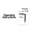
1-4-5. V Board
Removal 1. Remove the base assembly. (Refer to Section 1-3-1.) 2. Remove the rear cover and rear panel. (Refer to Section 1-3-3.) 3. Remove the two hooks of the rear panel, then remove the V board. 4. Disconnect the harness from the connector (CN30) on the V board.
1-4-6. Lamp Power Supply Board
Removal 1. Remove the cabinet. (Refer to Section 1-3.) 2. Remove the C board. (Refer to steps 3 to 6 of Section 1-4-1.) 3. Remove the lamp assembly. (Refer to steps 2 and 3 of Section 1-5-2.) 4. Remove the three screws and disconnect the harness from the connector (CN14) on the F board, then remove the lamp power supply unit. 5. Remove the two screws, then remove the lamp house. 6. Loosen the two screws, then remove the connector.
BTP 3 x 12 Lamp power supply unit
Rear panel
Hooks
CN30
BTP 3 x 12 Lamp house Screws
Harness
V board
Connector
Installation 5. Install the V board in the reverse order of steps 3 and 4. 6. Assemble this unit in the reverse order of steps 1 and 2.
Harness
CN14
F board
1-8
VPL-HS60/HS51A
|
|
|
> |
|