Shopping cart is empty
 
English Polski Spanish 
Search For a Manual
 

(e.g. AA-V20EG JVC, ZX-7 Sony )
PayPal 1000+ rating Secure, Encrypted Checkout.
 
Who's Online
There currently are 5908 guests online.
Categories
Information
Featured Product
Home >> SONY >> VPHG90E Service Manual
 
 0 item(s) in your cart 

SONY VPHG90E
Service Manual


Tweet about this product and get $1.00 of store credit for instant use!
  • Contains Circuit Diagrams
  • Download
  • PDF Format
  • Complete manual
  • Language: English
Price: $4.99

Description of SONY VPHG90E Service Manual

Complete service manual in digital format (PDF File). Service manuals usually contains circuit diagrams, printed circuit boards, repair tips, wiring diagrams, block diagrams and parts list. Service Manual ( sometimes called Repair Manual ) is used mainly by technicians.

If You just want to know how to use Your tv, video, mp3 player etc. You should look for Owner's Manual. After placing order we'll send You download instructions on Your email address.

The manual is available in languages: English

Not yet ready
You must purchase it first

Table of Contents
    1. CIRCUIT ADJUSTMENTS
      1. POWER BLOCK
        1. DC (+) Adjustment
        2. +115 V Adjustment
        3. +200 V Adjustment
        4. Oscillating Frequency Adjustment
      2. BA BOARD ADJUSTMENT
        1. Picture Control Adjustment
        2. Signal Level Adjustment
        3. Analog Test Signal Amplitude Adjustment
        4. ABL Adjustment
      3. CAR/CAG/CAB BOARDS ADJUSTMENT
        1. Preparation Before Adjustments
        2. Pedestal Level Adjustment
        3. CRT Protector Adjustment
        4. Cathode Level Adjustment
        5. G1 Level Adjustment
        6. VPS Limiter Adjustment
      4. DA/DB/DD BOARDS ADJUSTMENTS
        1. F/V Voltage Adjustment (DA Board)
        2. AFC Adjustment (DA Board)
        3. V Hold Adjustment (DA Board)
        4. H Parabola Waveform Adjustment (DA Board)
        5. H SIN Adjustment (DA Board)
        6. H SIN X VP Waveform Adjustment (DB Board)
        7. H SIN X V SIN Waveform Adjustment (DB Board)
        8. HS X VS Waveform Adjustment (DB Board)
        9. HP X V SIN Waveform Adjustment (DB Board)
        10. 1/2 SIN 1 Waveform Adjustment (DB Board)
        11. 1/2 SIN 2 Waveform Adjustment (DB Board)
        12. HS X VS Waveform Adjustment (DB Board)
        13. HP X VS Waveform Adjustment (DB Board)
        14. B KEY Waveform Adjustment (DB Board)
        15. T KEY Waveform Adjustment (DB Board)
        16. 1/2 H Switching Waveform Adjustment (DA/DB Boards)
        17. D/A Converter Offset Adjustment (DD Board)
      5. VCO OFFSET/LIMITER ADJUSTMENT
      6. YA BOARD REPLACEMENT
        1. Replacement Procedure
        2. Uploading Program (Emergency Mode)
        3. Creating Factory Data
        4. Creating Service Data
    1. OPERATING INSTRUCTIONS
      • Operation Instruction
      • Installation Manual for Dealers
    1. SERVICE INFORMATION
      1. CIRCUIT BOARDS LOCATION
        1. Location 1
        2. Location 2
        3. Location 3
      2. DISASSEMBLY
        1. Hood Removal
        2. Cover Removal
        3. Opening ED Block
        4. DC Board Removal
        5. EC Board Removal
        6. ED Board Removal
        7. E Board Removal
        8. Remote Commander Removal
        9. CB, CG and CR Blocks Removal
        10. DA, DB, DD, DE and DF Boards Removal
        11. EBH and EBQ Boards Removal
        12. HVB Block and High - Voltage Cable Removal
        13. DC Fan Removal
        14. PA and PD Boards Removal
        15. MD Board Removal
        16. HVF Block Removal
        17. BA and YA Boards Removal
        18. BC, F and ME Boards Removal
        19. EBB, EBG, EBR and PE Boards Removal
        20. GA and GB Boards Removal
        21. Lens Removal
          • (1) Picture Tube Removal
          • (2) Picture Tube Installation
        1. MA, MB and MC Boards Removal
        2. M Board Removal
        3. Extension Board
      1. ERROR CODE
        1. Warning Code on 7 - Segment LED
        2. Protector Code on 7 - Segment LED
        3. Error Code on 7 - Segment LED
      2. MEMORY ACCESS SYSTEM
        1. Memory Structure
        2. Various Memory Data
      3. MEMORY DATA RESET
    1. SET - UP ADJUSTMENTS
      1. PRECAUTIONS UPON ADJUSTMENT
      2. ATTACHING THE NECK ASSEMBLY
      3. ADJUSTING CONDITIONS
        1. Projecting System
        2. CRT Convergence Angle Check
      4. FOCUS ADJUSTMENT
        1. Preparations
        2. Focus Rough Adjustment
        3. DY Angle Adjustment
        4. MG FOCUS Coil Angle Adjustment
        5. 64 kHz Signal Registration Rough Adjustment
        6. RED/GREEN/BLUE Focus Adjustment
        7. Zenith Angle Adjustment
        8. HWC (H Width Coil) Adjustment
        9. Video Size Adjustment
        10. MG FOCUS Adjustment for 31.5 kHz Signal
        11. VIDEO Block MG FOCUS Adjustment
        12. MG FOCUS Adjustment for 64 kHz and 106 kHz Signals
        13. Adjustment of Other Frequencies
      5. REGISTRATION ADJUSTMENT
        1. INPUT MEMORY No. 0 Adjustment
        2. INPUT MEMORY No. 3 Adjustment
        3. INPUT MEMORY No. 5 Adjustment
        4. INPUT MEMORY No. 8 Adjustment
        5. Horizontal/Vertical Reverse Mode Centering Adjustment
      6. WHITE BALANCE ADJUSTMENT
        1. Preparations
        2. Color Temperature Adjustment with a Test Signal Generator
        3. Color Temperature Adjustment with No Test Signal Generator
      7. SIZE/SHIFT BLKG ADJUSTMENT
        1. SIZE/SHIFT/BLKG of Video/HDTV Adjustment
        2. Video Memory SIZE/SHIFT/BLKG Adjustments
      8. HIGH VOLTAGE SCREEN DISTORTION ADJUSTMENT
      9. PROCEDURE AFTER COMPLETING ADJUSTMENTS
    2. SAFETY RELATED ADJUSTMENT
      1. PA BOARD HV REGULATOR/HV PROTECTOR ADJUSTMENT
      2. CRT PROTECTOR ADJUSTMENT
    1. SEMICONDUCTORS
    2. EXPLODED VIEWS
      1. HOOD AND COVER BLOCK
      2. ED BLOCK
      3. HVF BLOCK
      4. CHASSIS BLOCK 1
      5. REAR BLOCK
      6. PICTURE TUBE BLOCK
      7. CHASSIS BLOCK 2
      8. BASE BLOCK
    3. ELECTRICAL PARTS LIST
      • Note: IFB - G90E Corresponds to the BD BOARD
    1. BLOCK DIAGRAMS
      • BA (1/3)
      • BA (2/3)
      • BD (Except VPH - G90E)
      • BA (3/3)
      • BB
      • BC
      • YA (1/4)
      • YA (2/4)
      • YA (3/4)
      • YB
      • YA (4/4)
      • DA
      • DB
      • DC
      • NA
      • DD (1/2)
      • DD (2/2)
      • DE (1/2)
      • DE (2/2)
      • DF
      • F
      • GA
      • GAA
      • GB
      • GBA
      • GBB
      • GC
    • L
    • ME
    • E
    • EA
    • ED
    • EBH
    • EBQ
    • EBR
    • EBG
    • EBB
    • PA
    • PB
    • MD
    • NB
    • PD
    • PE
    • CAR
    • CAG
    • CAB
    • CBR
    • CBG
    • CBB
    • CDR
    • CDG
    • CDB
    1. DIAGRAMS
      1. FRAME SCHEMATIC DIAGRAMS
      2. SCHEMATIC DIAGRAMS/PRINTED WIRING BOARDS
      • SCHEMATIC DIAGRAMS
    • BD
    • BA
    • BB
    • BC
    • YA
    • YB
    • DA
    • DB
    • NA
    • DC
    • DD
    • DE
    • DF
    • L
    • E
    • ED
    • EA
    • PA
      • PB
      • PD
      • NB
      • PE
      • EBA
      • EEC
      • EBB
      • EBG
      • EBR
      • EBH
      • EBQ
      • CAB
      • CBB
      • CDB
      • CAG
      • CBG
      • CDG
      • CAR
      • CBR
      • CDR
      • F
      • GA
      • GAA
      • GB
      • GBA
      • GBB
      • GC
      • M
      • MA
      • MB
      • MC
      • MD
      • EC
      • ME
    • PRINTED WIRING BOARDS
      • BD
      • BA
      • BB
      • BC
      • YA
      • YB
      • DA
      • DB
      • DC
      • NA
      • DD
      • DE
      • DF
      • L
      • E
    • ED
    • EA
    • PA
    • PB
    • PD
    • NB
    • PE
    • EBA
    • EBC
    • EBB
    • EBG
    • EBR
    • EBH
    • EBQ
    • CAB
    • CBB
    • CDB
    • CAG
    • CBG
    • CDG
    • CAR
    • CBR
    • CDR
    • F
    • GA
    • GAA
    • GB
    • GBA
    • GBB
    • GC
    • M
    • MA
    • MB
    • MC
    • MD
    • EC
    • ME
    • OVERVIEW
      • Precautions
      • Features
      • Location and Function of Controls
        • Front
        • Rear
        • Remote Commander/Control Panel
    • PROJECTING
      • Projecting
      • Adjusting the Picture
      • Centering Adjustment
      • Adjusting the Size and Shift of the Picture
        • SIZE Adjustment
        • SHIFT Adjustment
        • Blanking Adjustment
    • ADJUSTMENTS AND SETTINGS USING THE MENU
      • Using the Menu
        • Basic Menu Operation
        • Menu Modes
      • The PIC CTRL (Picture Control) Menu
      • The PIC SETTING 1 (Picture Setting 1) Menu
      • The PIC SETTING 2 (Picture Setting 2) Menu
      • The INPUT SETTING Menu
      • The SET SETTING 1 Menu
      • The SET SETTING 2 Menu
      • The INPUT INFO (Information) Menu
      • The SET INFO (Information) Menu
    • INSTALLATION/CONNECTION EXAMPLES
      • Installation Examples
        • Installation 1: Floor Installation Using Front Projection Flat Screen
        • Installation 2: Ceiling Installation Using Front Projection Flat Screen
      • Connection Examples
        • Connecting Directly to the Projector
        • Connecting Multiple Projectors
        • Using the PC - 3000 Signal Interface Switcher
        • Confirming the System Construction
        • Using the PC - 1271/1271M Signal Interface Switcher
      • Setting the Index Numbers
    • MAINTENANCE/OTHER
      • Troubleshooting
      • Specifications
      • Index
Customer Reviews
There are currently no product reviews.
Other Reviews
 KGIE3200/A BAUKNECHT Service Manual by Kees Renard;
exactly as they say. Within 24 hours the link to the pages and offcourse it was the right service manual. Super and thanks
 824876690 CLARION Service Manual by Alexander Volmer;
The manual was exact the thing that was promised. My old car stereo is working again thanks to the information supplied.
 CDR20 HARMAN KARDON Service Manual by CARLOS LOPEZ;
I PURHASED THIS PRODUCT BECAUSE I WAS HAVING PROBLEMS WITH MY CDR20 HARMAN KARDON RECORDER. WHICH I PURCHASED NEW 12 YEARS AGO. AFTER REVIEWING THE MANUAL, I WAS ABLE TO ADJUST THE TENSIONER IN THE SYSTEM. WORKS LIKE A CHAMP!. SAVED ME AT LEAST 100.00 WHICH WAS WHAT A SERVICE REPAIR STATION WANTED. GREAT MANUAL EASY TO READ. SPECIALLY AFTER I PRINTED THE PAGES WHICH DEALT WITH MY RECORDER. THANKS A LOT!!!!!!!!
 ZSX5000 SONY Service Manual by Diogo Silva;
You can fully trust on this one! All the schematics are very crear an in one piece per page
 Z-5000 TEAC Service Manual by MESUT BALCI;
I have never bought a service manual which is as competely readable as this althogh it was a scanned pdf. Thank you for this succesful manual also cheaper than other sites.

Text excerpt from page 189 (click to view)
3-7-2. Video Memory SIZE/SHIFT/BLKG Adjustments
1. Input the monoscope signal to VIDEO IN. 2. Press the INPUT SELECT VIDEO key to project the monoscope signal on the screen. 3. Select VIDEO MEMORY 1 using the SWITCHER/ VIDEO MEMORY/INDEX changing switch and the SWITCHER/VIDEO MEMORY/INDEX key. 4. Press the RGB SHIFT key and adjust the center of the monoscope signal to the screen center using the �, �, � and � keys. 5. Press the RGB SIZE key and adjust the horizontal and vertical sizes of the monoscope signal to 4:3 using the �, �, � and � keys. 6. Press the BLKG key to adjust the screen top blanking to the position 40 ± 10 mm outside the effective screen using � and � keys. 7. Press the MEMORY key. 8. Store the data of VIDEO MEMORY 1 to VIDEO MEMORY 2 to 5, too. 9. Select VIDEO MEMORY 6. 10. Press the RGB SHIFT key and adjust the center of the monoscope signal to the screen center using the �, �, � and � keys. 11. Press the RGB SIZE key and adjust the horizontal and vertical sizes of the monoscope signal to 4:3 using the �, �, � and � keys. 12. Press the BLKG key to adjust the screen top blanking to the position 40 ± 10 mm outside the effective screen using � and � keys. 13. Store the data of VIDEO MEMORY 6 to VIDEO MEMORY 7_10, too.

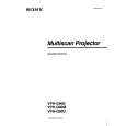
3-8. HIGH VOLTAGE SCREEN DISTORTION ADJUSTMENT
1. Select INPUT A and input the fH = 64 kHz RGB stripe signal to the RGB terminals. 2. Press CONTR (+) and BRIGHT (+) to set the contrast and bright levels to the maximum. 3. Adjust RV1 of the EA board so that the left and right vertical lines of the stripes can be straight.

NG

OK

3-9. PROCEDURE AFTER COMPLETING ADJUSTMENTS
After completing all adjustment, change the dip switch S201-1 on the YA board from �OFF (right)� to �ON (left)� to save the adjustment data in the memory.

VPH-G90E/G90U/G90M

3-19

You might also want to buy

$4.99

VPHG90E SONY
Owner's Manual

Complete owner's manual in digital format. The manual will be available for download as PDF file aft…
>
Parse Time: 0.613 - Number of Queries: 110 - Query Time: 0.2