I ordered this manual sometime in the afternoon and I received it on my e-mail the same evening.
This is a fantastically good and properly scanned copy of the original manual. All pages are of the same scale and they overlap each other. It means that you can print the manual and easily make it as a convenient paper manual.
The content of the manual is fantastic. Alignment descriptions, PCB layouts and elementary diagrams are explicit and precise. I immediately found what I was looking for. Thanks to this manual and Owner-Manuals.com my amplifier is alive again. Many thanx indded!
The manual was well-scanned and easy to read. As an added bonus, the Operator's Manual was bundled with the Service Manual!
I'd definitely use owner-manuals.com again.
Text excerpt from page 32 (click to view)
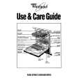
5-2. Replacing the CPU
1. Removing the CPU
1 Insert a flat-blade screwdriver into the notch as shown in the illustration and rotate it so that the protrusion comes to the lock release position. 2 Pull the CPU gently upward to lift it out of the CPU socket.
2. Installing the CPU
1 Align the triangle reference mark of the CPU with that of the CPU socket and insert all the pins of the CPU to the corresponding holes of the CPU socket. 2 While pressing the two positions marked by a, insert the flat head (-) screwdriver into the specified position and rotate the screwdriver to the LOCK position.
1
2
1 CPU Lock position 2
2 CPU Lock release position Reference marks 1
Lock release position
CPU socket
Lock position
CPU socket
NOTE: Rotate a flat-blade screwdriver to the lock position securely. If not, the operation of the CPU may become unstable.