I am only search for 5 Minute, by it in 5 Minutes to and get ist in few ours! Best i found in the Internet and my Amplifer is repaired as well! Thank you
I found the manual to be clear concise and complete. It was of immense assistance when removing the unit as the unit was over 22 years old and the wiring diagram was unobtainable from the manufacturer. The exploded drawings were clear as were the instructions and labels.
Text excerpt from page 16 (click to view)
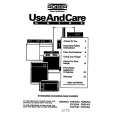
3. Top Cover/Under Cover (1) (2) (3) (4) Remove the side cover. (Refer to Section 2-1-2.2) Disconnect one harness from the MEC-13 board. Remove one screw, then remove the six hooks. Remove the top cover in the direction indicated by the arrow.
2-1-3. Replacement of Main Parts
1. Replacement of SE-611 Board (1) Remove the side cover. (Refer to Section 2-1-2.2) (2) Disconnect one harness from the SE-611 board. (3) Remove the two screws, then remove the SE-611 board.
Top cover
Top cover
Hooks Harness MEC-13 board
Hooks
Harness
BVTP 3x12
Roller shaft B Align the mating faces Hole Align the mating faces
BVTP 3x6
SE-611 board
(4) Attach a new SE-611 board in the reverse order of steps (1) to (3). 2. Replacement of MEC-13 Board
Roller shaft A Hole Under cover
(5) Attach the top cover in the reverse order of steps (1) to (4). n When attaching the top cover, make sure to align the mating faces before inserting the roller shafts A and B into each hole.
(1) Remove the side cover. (Refer to Section 2-1-2.2) (2) Remove the top cover and under cover. (Refer to Section 2-1-2.3) (3) Disconnect the five harnesses from the MEC-13 board. (4) Remove the three screws, then remove the MEC-13 board.
BVTP 3x8 Harness Harnesses
Harness
MEC-13 board
Under cover
(5) Attach a new MEC-13 board in the reverse order of steps (1) to (4). 2-2 (E)
UYA-S90SF