Great manual...really saved me. The only problem is that I thought I would be able to download it directly when I paid for it but never received the download instructions until the next morning. The board trace pages were somewhat light also: really need to turn up the contrast on the printer before printing them. The schematic page was great; very clear! Well worth the money.
I've been in the electronic business for a long time. I used to buy Sam's Photofact for my needs which intailed having to go to the store and paying about $20 for a package of 3 different units so I was forced to buy more than I needed just to get one.
Owner manual is just at your keyboard and the information is almost instantansouly and the cost is very reasonable. Easy to print out if needed or simply read off of the screen. The larger the screen the better for obvious reasons.
Only thу cover has poor quality, internal material has excellent quality - exactly what I needed
Thanks!
Text excerpt from page 13 (click to view)
3) Observe the waveform on the spectrum analyzer and turn RV21 to adjust the modulation degree of a sub spectrum �A� in the figure 4 to be narrowest as shown below.
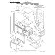
4) At this time, measure AC voltage of IC21 Pin 1 on the TX board with AC voltmeter and define the value as �V0� for the next adjustment. 5) Turn the RV21 again so that the AC voltage of IC21 Pin 1 becomes the same value as the two thirds of �V0�. (V1=V0 � 2/3) Adjustment Location: TX board (See page 6.) Adjustment and confirmation without a spectrum analyzer Please confirm the units by following procedure shown below. Here a series of procedure which can be performed without a spectrum analyzer is introduced. Deviation adjustment/confirmation 1) Input a 400 Hz 316 mV signal into the left channel of transmitter. 2) Measure the AC voltage at the Pin 1 of IC21 (MJM2100M) with AC voltmeter. Spec.: 100 ± 10 mVrms If not, turn RV21 for obtaining the value. Adjustment Location: TX board (See page 6.) Sub-carrier frequency and output level confirmation 1) No signal is input into transmitter. 2) Connect a oscilloscope and a frequency counter to the test point TP1. 3) Confirm the voltage is within the following spec. Spec.: 0.55 Vp-p
0.55 Vp-p
4) Confirm the frequency is within the following spec. fsub=42 ± 2 kHz
SCHEMATIC DIAGRAM
� Original Service Manual page 7. (Location C � E, 6 � 8) Connection point
PRINTED WIRING BOARD
� Original Service Manual page 5. (Location A � C, 4 � 6)
oscilloscope frequency counter IN