|
|
|
Who's Online
There currently are 6043 guests online. |
|
Categories
|
|
Information
|
|
Featured Product
|
|
|
 |
|
|
There are currently no product reviews.
 ;
Awesome manual. Complete diagrams of all board assemblies as well as how to get to each part of the t.v. down to the individual screws and their locations. Get it.
;
perfect copy, im very satisfied, i was need the diagram over the powersupply and
the copy was very sharp
;
This is exactly the service manual I needed.
Complete with all schematics, partslists, PCB layouts and alignment instructions.
This manual covers both the T-4970 en T-488F Onkyo tuner.
 ;
IF PRINTED CIRQUIT BOARD WIRING VIEW WAS ONE TONE LIGHTER, THEN 5 STAR RANK HAS TO BE MY CHOISE.
;
Very usefull, good quality drawings !
Muito útil encontrei todas as informações necessárias.
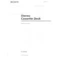
Record/Playback Head Azimuth Adjustment DECK A Procedure: 1. Forward Playback Mode
test tape P-4-A100 (10 kHz, �10 dB) 47 k� set level meter
DECK B
Tape speed Adjustment Adjust DECK A first Procedure: � Forward Playback Mode �
test tape WS-48B (3 kHz, 0 dB)
DECK A
DECK B
frequency counter 47 k� set
LINE OUT
LINE OUT
2. Turn the adjustment screw for the maximum output levels. If these levels do not match, turn the adjustment screw until both of output levels match together within 1 dB.
L-CH peak
output within 1 dB level
within 1 dB
(High speed adjustment) 1. Press the PITCH CONTROL button to set to OFF . 2. Set to test mode. (Refer to page 11.) 3. Press the · button to playback. 4. Press the HIGH/NORMAL button to playback at double speed. 5. Adjust RV316 (DECK A), RV416 (DECK B) so that the frequency counter reading becomes 5,980 ± 180 Hz. (Normal speed adjustment) 6. Press the · button to playback. 7. Press the HIGH/NORMAL button to playback at normal speed. 8. Adjust RV317 (DECK A), RV417 (DECK B) so that the frequency counter reading becomes 3,000 ± 90 Hz. (Pitch control adjustment) (DECK A) 9. Press the PITCH CONTROL button to set to ON . 10. Set PITCH CONTROL knob to mechanical center. 11. Press the · button to playback. 12. Adjust RV318 so that the frequency counter reading becomes 2,990 ± 90 Hz. Adjustment Location: MAIN board (See page 14.)
screw position
R-CH peak L-CH peak R-CH peak
screw position
3. Playback Mode
test tape P-4-A100 (10 kHz, �10 dB) L-CH 47 k�
oscilloscope
set
V
H
Sample value of wow and flutter W.RMS (JIS) less than 0.3% . (test tape : WS-48B) Playback Level Adjustment Procedure: � Forward Playback Mode �
test tape P-4-L300 (315 Hz, 0 dB) 47 k�
DECK A
DECK B
R-CH
47 k� LINE OUT Screen Pattern
level meter
In phase
45� good
90�
135�
180�
set
wrong
LINE OUT
4. Change the reverse playback mode and repeat the steps 1 to 3. 5. After the adjustment, lock the adjustment screws with suitable locking compound. Adjustment Location: � record/playback head �
Adjust DECK A : RV111 (L-CH), RV211 (R-CH) and DECK B : RV121 (L-CH), RV221 (R-CH) so the level meter reading becomes the adjustment limits below. Adjustment Value: LINE OUT level : �7.7 ± 0.5 dB (0.301 to 0.338 V) Level difference between channels : within 0.5 dB Confirm that the LINE OUT level does not change in playback mode while changing the mode from playback to stop several times.
reverse side
forward side
Adjustment Location: MAIN board (See page 14.)
adjustment screws
� 12 �
|
|
|
> |
|