|
|
|
Who's Online
There currently are 6043 guests online. |
|
Categories
|
|
Information
|
|
Featured Product
|
|
|
 |
|
|
There are currently no product reviews.
 ;
Excellent service manual includes everything is need to repair this radio-caseete, how to disassemble, wiring diagram, all , waiting time until the download was only a few hours. I'm going to buy service manuals from here, are cheap and very good.Thank you.
;
Good service manual,i saved from scrapping this deck,is now fully functional.Thanks.
 ;
Found this to be the manual included with the original packinging, was helpfull but did not give any detailed repair instructions.
;
Complete service manual, was very helpful in repairing this tapedeck.Thanks.
;
The service manual was a copy of the original from Wirlpool. The quality was good, all neccecary information was available including the service-codenumbers, so I could order the right part to be replaced for repair.
Downloding was no probem after the payment.
Thanks for the service!
SECTION 5 ELECTRICAL ADJUSTMENTS
Precaution � Supplied voltage: 2.5 V � Switch and control position VOR switch (S104): OFF PAUSE switch (S105): OFF VOL (RV101): mechanical mid SPEED CONTROL (RV602): mechanical center Test Tape
Type P-4-A063 WS-48A Signal 6.3 kHz, �10 dB 3 kHz, 0 dB Used for head azimuth adjustment tape speed adjustment
Tape Speed Adjustment Procedure: Mode: playback
Standard tape for adjusting WS-48A (3 kHz, 0 dB) 10 k � set EAR jack
+ �
frequency counter
1. Play back WS-48A (tape end part) and adjust RV601 so that the frequency counter reading becomes 3,000 ± 15 Hz. 2. Play back WS-48A tape the beginning and the end part, check that the frequency counter reading is within same standard of step1. Adjustment Location:
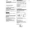
0 dB=0.775 V Record/Playback Head Azimuth Adjustment Procedure: Mode: playback
test tape P-4-A063 (6.3 kHz, �10 dB) 10 k � set EAR jack
+ �
level meter
[MAIN BOARD] (Conductor side)
1. Turn the adjustment screw to obtain the maximum reading on level meter.
Note: Several peaks may appear, but take the maximum.
IC101
2. After the adjustment, lock the adjustment screw with suitable locking compound. Adjustment Location:
RV601
adjustment screw
�8�
|
|
|
> |
|