|
|
|
Who's Online
There currently are 5612 guests online. |
|
Categories
|
|
Information
|
|
Featured Product
|
|
|
 |
|
|
There are currently no product reviews.
 ;
this manual make me repair my vintage radio with easily.
Thank you for your best service
sukpra
;
A good manual. Had everything i needed to make the repair.
;
This manual is a complete guide, including later additions. It has all the necessary information about the replacement items. The material quality is great to read.
 ;
This manual is very helpful, correct shematic diagram, and good exploded view.Perfect!
;
Alte gescannte Servicepläne sind oft doch etwas undeutlich . Stromlaufpläne werden auf mehrere DIN A4 Seiten aufgeteilt. Alles ziemlich umständlich und zeitaufwendig. Aber mit etwas Mühe geht alles.
TA-VE110 SECTION 4 EXPLODED VIEWS
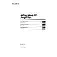
3-4. IC BLOCK DIAGRAMS
NOTE: � -XX, -X mean standardized parts, so they may have some differences from the original one. � Items marked �*� are not stocked since they are seldom required for routine service. Some delay should be anticipated when ordering these items.
4-2.
� � The mechanical parts with no reference number in the exploded views are not supplied. Abbreviation G: German model EE: East European model
The components identified by mark ! or dotted line with mark ! are critical for safety. Replace only with part number specified.
CHASSIS SECTION
IC201 LC7822
1 IN 2 3 OUT 4 5 IN 6 7 OUT 8 9 IN 10 OUT VEE 11 12
CONTROL
IC202 LA2785
30
IC203 LV1011
ROUT SOUT
56
T101 #1 not supplied
#1 not supplied
1
29 IN 28 27 OUT 26 25 IN 24 23 OUT 22 IN 21 LEVEL SHIFT 20 OUT 19 VDD LATCH 18 RESET 17 S SHIFT RESISTOR 16 VSS
NOISE FILTER
NOISE CH BALANCE CONTROL VR CONTROL
LPF NOISE GENERATER
24
23
22
21
20
19
18
17
16
15
14
13
CONTROL
2
42 41 40 39
CLK DATA LATCH
VSS
4-1.
(BUILTED IN VDD) OUT AD DA IN OUT IN B SW2 A REF VREF B CONTROL LOGIC OUT IN 12k SRAM IN B SW2 A C A B SW2 B REF OUT 7k L.P.F IN IN 20k L.P.F OUT A B REF VREF OUT NR IN 20k A B SW2 CONTROL B SW2 A REF VREF B REF B B SW2 REF VREF EFECT SW OUT B SW2 A B REF VREF
FRONT PANEL SECTION 10 10
#1
60
#4
60
3
V REF
55 53 54
#3 F151 #3
DEVIDER
OSC
57
#1 #4 #2 #1 #1 #2
4 5 6 7
CLK
59
AEP, G, EE UK
B SW3
DATA LAT
38 8 LIN 9 VR 37 RIN 10 VR 36
VCC
B
66
VDD
LOUT
IN
S-TRIM
OUT
#1
#1 #1
ROUT
CE 13 DI 14
9
A
chassis section
#1
#1
53
F152, F153 not supplied T151 not supplied
VSS
11
LIN
A B
CL 15
65 64
#1
#1
10 8
11 12
CMODE
VCA VCA VCA
VCA VCA VCA LPF
CTRIM
RIN
VCA
VCA
35
SOUT
VREF
14
VCC
32
REVOUT
MUTE
33
SIN
34
COUT
1
2
3
4
5
6
7
8
9
10
7 14
61
#1
5
AGND
P. S.
31
12 13 14
LPF 30 29
3 11 6
LOUT
A
� RECT RECT RECT
+ RECT
14
not supplied
15 16 17 18
28 27 26 25
IC404 NJM2103D
4 16 13
12
#1
51
19 LOG DIFF
24
CR
1
8
RESET
DUAL T CONTROL
2
#1
20 21
LOG DIFF
23 22
VSC 2
+�
�
+
16 1 Supplied
with RV611 #1
VREF
7
VSA
VREF
15
Remarks Ref. No. *9 10 11 * 12 13 14 15 16 Part No. 4-980-193-21 3-704-366-01 1-773-215-11 A-4392-561-A Description CASE (408226) SCREW (CASE) (M3X8) WIRE (FLAT TYPE) (25 CORE) DISPLAY BOARD, COMPLETE Remarks
Ref. No. 51 53 * 54 * 55 * 56 * 57 * 59 !60 !60 * 61
Part No. X-3371-405-1 1-533-293-11 1-664-612-11 1-664-611-11 1-659-839-11
Description FOOT (SMALL) ASSY FUSE HOLDER TRANS BOARD POWER BOARD POWER CONNECTION BOARD
Remarks
Ref. No. * 61 * 64 * 65 66 ! F151 ! F152 ! F153 ! T101 ! T151
Part No. 4-988-714-11 1-664-608-11 A-4392-566-A 4-956-370-02 1-532-501-51
Description PANEL, BACK (UK) VOLUME BOARD MAIN BOARD, COMPLETE BAND, PLUG FIXED (UK) FUSE (T800mA/250V)
Remarks
OUTC
3
6
VSB/SESIN
Ref. No. 1 2 3 4 5 6 7 *8
Part No. 4-980-041-01 4-980-035-11 X-4948-093-1 4-963-404-21
Description KNOB (VOL) WINDOW PANEL ASSY, FRONT EMBLEM (5-A), SONY
GND
4
Q R S + � +�
5
V+
4-980-039-01 BUTTON (LEVEL) 4-980-040-01 BUTTON (FUNCTION) 3-931-429-01 BUTTON (POWER) 1-664-610-11 POWER SWITCH BOARD
4-980-038-01 BUTTON (SURROUND) 4-951-620-01 SCREW (2.6X8), +BVTP 4-977-593-11 RING (DIA. 50), ORNAMENTAL 4-977-358-11 CUSHION (8X12.5)
3-309-144-21 HEAT SINK 3-703-244-00 BUSHING (2104), CORD 1-696-571-11 CORD, POWER (UK) 1-777-071-11 CORD, POWER (AEP, G, EE) 4-988-714-01 PANEL, BACK (AEP, G, EE)
1-532-465-51 FUSE, TIME LAG (T3.15A/250V) 1-532-465-51 FUSE, TIME LAG (T3.15A/250V) 1-431-145-11 TRANSFORMER, POWER 1-431-146-11 TRANSFORMER, POWER
� 18 �
� 19 �
� 20 �
� 21 �
� 22 �
The components identified by mark ! or dotted line with mark ! are critical for safety. Replace only with part number specified.
|
|
|
> |
|