|
|
|
Who's Online
There currently are 5785 guests and
2 members online. |
|
Categories
|
|
Information
|
|
Featured Product
|
|
|
 |
|
|
There are currently no product reviews.
 ;
Very useful service manual, was exactly what i needed.Good quality,reasonable price.Thank you.
;
Acurate informations inside the SM and I could repair my old Sansui SC-3330 without any problems. Thanks.
;
I used it to repair a NAD 7030, but unfortunately, the 7045 is different !
But documentation was useful.
;
Content A4 and A3 format pages. Exactly what I needed to restore my old receiver.
;
Content A4 and A3 format pages. Exactly what I needed to restore my old receiver.
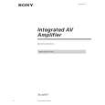
SECTION 3 DIAGRAMS
3-1. CIRCUIT BOARDS LOCATION
THIS NOTE IS COMMON FOR PRINTED WIRING BOARDS AND SCHEMATIC DIAGRAMS. (In addition to this, the necessary note is printed in each block.) NOTE
� � : parts extracted from the component side. : Pattern from the side which enable seeing.
8MHz
3-2. WAVEFORMS MAIN SECTION 1
5.2Vp-p
NOTE
T-1 board POWER board
� All capacitors are in µF unless otherwise noted. pF : µµF 50WV or less are not indicated except for electrolytics and tantalums. � All resistors are in � and 1/4W or less unless otherwise specified. � ¢ : internal component. � : nonflammable resistor. � : panel designation. Note: The components identi-fied by mark ! or dotted line with mark ! are critical for safety. Replace only with part number specified. � B+ : B+ Line � B� : B� Line � Voltage and waveforms are dc with respect to ground under nosignal conditions. no mark : STOP � Voltages are taken with a VOM (Input impedance 10M�). Voltage variations may be noted due to normal production tolerances. � Waveforms are taken with a oscilloscope. Voltage variations may be noted due to normal production tolerances. � Circled numbers refer to waveforms. � Signal path. : FM
IC202 @¢
T-2 board
PANEL SECTION 2
REAR SP board
4.2Vp-p
5MHz
IC401 #¢ X1
H.P board
MAIN board DISPLAY board
VR board
�5�
�5� 6
 $4.99 TAAV571 SONY
Owner's Manual Complete owner's manual in digital format. The manual will be available for download as PDF file aft…
|
|
|
> |
|