|
|
|
Who's Online
There currently are 6043 guests online. |
|
Categories
|
|
Information
|
|
Featured Product
|
|
|
 |
|
|
There are currently no product reviews.
 ;
Perfect source for service manuals: fast and professional transaction; high quality, perfect readable and largely scaleable PDF; complete schemes, diagrams and spare part list. Tnx a lot, cu again!!!!
;
I got your link from a friend and I must say that I am really satisfied with your service. Specially this B&O manual I didn't find anywhere on the web... but you could deliver it :-) . You deliver very fast and the copy is of good quality. So your webpage is bookmarked. Thanks
;
This was the Sony CCU-500A Service manual I was looking for.
The price was reasonable.
The permission to download was quck.
I will use Owner-Manual.com for all my manual needs.
;
Excellent printing quality.
A complete and very usefull service manual with all details.
GREAT SERVICE AT VERY LOW PRICE!
A+++++++++++++++++++++++++
;
Excellent printing quality.
A complete and very usefull service manual with all details.
GREAT SERVICE AT VERY LOW PRICE!
A+++++++++++++++++++++++++
4-4-9. Color Reproduction
1 Press the step forward button once. The mode indicator will display �03�. 2 Shoot the color bar chart. 3 Adjust the lens iris so that the VIDEO-OUT white image level is set to 90 ± 2.5 IRE (NTSC) or 630 ± 15 mV (PAL).
Subject Measurement point Equipment Display Mode Specification Color Bar Chart White image level of VIDEO OUT Waveform Monitor 03 90 ± 2.5 IRE (NTSC) 630 ± 15 mV (PAL)
4-4-10. WB Data Take-in
1 Press the commander�s step forward button once. The mode indicator will display �63� and the data indicator will displays �02�. 2 Shoot the all-white pattern. 3 Adjust the lens iris so that the image level of the VIDEO-OUT value is set to 65 ± 3 IRE (NTSC) or 455 ± 20 mV (PAL).
Subject Measurement point Equipment Display Mode Specification All white pattern White image level of VIDEO OUT Waveform Monitor 63 65 ± 3 IRE (NTSC) 455 ± 20 mV (PAL)
White Image Level
4 Press the data up button of the commander so that the data indicator displays �03�. 5 Make sure that the data indicator of the commander automatically displays �FF�. * If the data indicator does not display �FF�, there may be a defective part in the circuit. Repair it, then repeat these steps.
4-4-11. Data Write
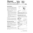
4 Switching the mode between �03�, �04�, �05� and �06� by pressing the MODE DISPLAY CHANGE button and while doing so, press the data change button so that the center of the bright spot for each color is placed in it�s respective reproduction range.
Subject Measurement point Equipment Display Mode Specification Color Bar Chart Respective color bright spot of VIDEO OUT Waveform Monitor 03, 04, 05, 06 The center of the bright spot for each color is in it�s respective reproduction range
1 Press the step forward button of the commander once. The LCD indicator will turn off for a few seconds, then turn on. Make sure that the data indicator displays �00�. (The mode indicator should still display �63�.) * If the LCD indicator turns off and does not turns on, or the data indicator does not display �00�, there may be a defective part in the circuit. Repair it, then repeat these steps. Note: In this time, do not press the DATA write (PAUSE) button.
(a) (b) (c) (d)
(a) Moving direction of the bright spot when mode is �03� (b) Moving direction of the bright spot when mode is �04� (c) Moving direction of the bright spot when mode is �05� (d) Moving direction of the bright spot when mode is �06�
SSC-DC50A/54A SSC-DC50AP/54AP/58AP
4-7
|
|
|
> |
|