|
|
|
Who's Online
There currently are 6031 guests online. |
|
Categories
|
|
Information
|
|
Featured Product
|
|
|
 |
|
|
There are currently no product reviews.
 ;
This service manual helped me to repair my PIONEER. Iam very satisfied, that I found it here.
Even the price of manual was not so high that person would not be able to spend a few money.
But that is very worth spent money. Thanks
 ;
Excellent quality service manual. Quick processing, fair prices. Love to do business again. Thank you!!!
;
Excellent service manual, the only known point of note is the alignment of improvability scanned pages within the pdf page. The resolution is good.
;
I was very glad recieving the service manal from You. Additionaly very fast. Extremaly nice servicing. Thanks very mach! Now my GX-220 working better, than it was made. Alexander from Moscow, Russia/
;
Sweet! I won the item on eBay and couldn't adjust the geometry or even keep a steady picure. This guide has the full schematics (not available anywhere else as far as I could tell), and was a bargain for the wealth of knowledge it contains. I hooked it up to my testing equipment, tweaked a few potentiometers and got it playing videogames in no time. Thanks!
HiFi Switching Position Adjustment (MA-370 Board) [Adjustment Purpose] To adjust the link of the A-ch and B-ch of the tape playback outputs. To make the unit compatible with other tapes and units. If this specification is not satisfied, the link will appear on the screen and the screen will be disrupted, etc. Mode Signal Measurement point Measuring instrument Adjusting element Specified value Playback Alignment tape: SP color bar portion CH1: Pin 1 of CN270 (HF ADJ) CH2: Pin 3 of CN270 (RF SWP) Oscilloscope Remote Commander CH +/� B=minimize
2-4-2.
2-4-3. Normal Audio System Adjustment � Make adjustment in the SP mode unless otherwise specified. Use a normal VHS cassette for an adjustment tape. � Set AUDIO MONITOR to normal. 2-4-4. ACE Head Adjustment Refer to the VHS mechanical adjustment manual MECHANISM) (9-921-647-11).
(S
2-4-5. E-E Output Level Check [Adjustment purpose] Confirm that the output level adjust the reference input is within the specification. Mode Signal Measurement point Measuring instrument Specified value E-E 400 Hz, �7.5 dBs J561 L/R Audio level meter �7.5 ± 2 dBs
[Adjustment Method] 1) Check that �A H� is indicated on FL display. 2) 3) 4) 5) Adjust so that part B becomes minimized at CH +/�. Write data EEPROM by pressing PAUSE button. Check that �A H� indicator turns off. If �A H� indicator is still on, restart RF switching position Adjustment from the beginning.
B
[Check Method] 1) Input signal of 400 Hz and �7.5 dBs to the J561 L/R. 2) Check that the audio output level is �7.5 ± 2 dBs. 2-4-6. Frequency Response Check [Adjustment purpose] Confirm that the frequency characteristic is within the specification. Mode Signal Measurement point Measuring instrument Specified value REC and PB (SP mode) 400 Hz, �17.5 dBs 7 kHz, �17.5 dBs J561 L/R Audio level meter 0 ± 3 dB
CH1 HFADJ CH2 RF SWP
Note: Tape path adjustment must have been completed.
Fig. 6-2-5
[Confirmation Method] 1) Supply a signal of 400 Hz, �17.5 dBs to J561 L/R. 2) Connect the audio level meter to J561 L/R. 3) Adjust the attenuator so that the audio level meter will indicate �27.5 dBs. 4) Make recording in the SP mode. 5) Set an audio line input signal to 7 kHz and make recording. 6) Playback a recorded portion, and measure output levels at 400 Hz and 7 kHz. 7) Confirm that the 7 kHz playback output level within a range of the 400 Hz playback output level 0 ± 3 dB.
6-4
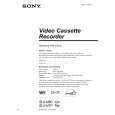 $4.99 SLVN80 SONY
Owner's Manual Complete owner's manual in digital format. The manual will be available for download as PDF file aft…
|
|
|
> |
|