|
|
|
Who's Online
There currently are 6032 guests online. |
|
Categories
|
|
Information
|
|
Featured Product
|
|
|
 |
|
|
There are currently no product reviews.
 ;
There was no problem at all.After paying i had to wait only a few hours,than i could
download the manual in best pdf-quality.
Thank You !
 ;
I found this service manual to be complete in every detail except for troubleshooting charts. It would be helpful if it had a set of troubleshooting charts; however it is a very good manual otherwise and for the price it is very well worth it.
;
Complete manual included schematics layouts and alignment procedure, clear to read and magnify, extremely pleased with manual and owner manual . com's service
;
perfect, i am very satisfait for the réception of the sansui r-5l service manual, thank you very much
;
Thank you, this is a rare document. Few others have it, but they charge way more for a download.
Great deal (even if you have to wait a few hours to get it).
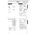
[Adjustment Method] 1) Short-circuit between pin 5 (AV ADJ) and 3 (GND) of CN261 for about 1 second to activate the RF switching position adjustment mode. 2) Check that �AF� is indicated on FL display. 3) Using the program + and � buttons, adjust to 416 ± 32µsec (6.5 ± 0.5H). 4) Press the PAUSE button. 5) The set goes to the AF switching position adjustment mode.
2-4. VIDEO SYSTEM CHECKS For the video system checks, follow the checking procedures given below as a rule. The color bar video signal supplied from the pattern generator is used as the video input signal for the video system adjustment of the recording mode. Check that the signal satisfies the specified value designated in the �Check of input signal� (Fig. 6-2-2) Unless otherwise specified, set the switches to the following positions. � INPUT SELECT switch ................................................. LINE 1 � TAPE SPEED switch ............................................................ SP [Checking Sequence] 1) X�tal OSC Check 2) SYNC AGC Check 3) White clip/Dark clip Check 4) Recording Y Level Check 5) Recording Chroma Level Check 6) Playback Level Check 2-4-1. Mode X�tal OSC Check (MA-316 Board) Playback Alignment tape: SP Color bar portion Q211 Emitter Oscilloscope and Frequency counter 4,433,619 ± 96Hz
CH1
Approx. 1Vp-p Approx. 5Vp-p V Enlargement Vertical sync. signal
CH2
CH1
CH2 (CN261 PIN 2 (RF SWP)) (RP-231)
6.5 ± 0.5H (416 ± 32 µsec)
Signal Measurement point Measuring instrument Specified value
Fig. 6-2-3
6) 7) 8) 9) Check that �AH� is indicated on FL display. Using the program + and � buttons, minimize a chipped portion. At this time, confirm that a noisy sound is not heard. Press the PAUSE button. Press the EJECT button.
CH2 RF SWP (CN261 PIN 2) (RP-231)
Note: A frequency counter should be connected through a buffer amplifier (oscilloscope, etc.) having a high impedance and a low capacitance. [Check Method] 1) Check that the oscillation frequency satisfies the specified value and that the oscillation voltage is 500 ± 200mVp-p.
500 ± 200mVp-p
CH1 OK HF ADJ (CN341 PIN 1) (RP-231) NG
4,443,619 ± 96Hz
Fig. 6-2-5
Should be minimized RF signal dropout
Fig. 6-2-4
6-3
|
|
|
> |
|