|
|
|
Who's Online
There currently are 5886 guests online. |
|
Categories
|
|
Information
|
|
Featured Product
|
|
|
 |
|
|
There are currently no product reviews.
 ;
Perfect, complete manual, exactly what I needed. Recommended to everyone.
;
Very usefull manual. From my point of view there are needs more clearables images.
;
Once again owner-manual.com has saved the day for me, and come through with the manual I need. I looked other places too, and couldn't find it anywhere. Thank You owner-manual.com!!! You're the BEST!
;
very good quality that can be magnified several times, and it remains readable.
For sure I will return next time the need for a service manual arise.
;
The service manual is really great - thanks to it I was able to install the laser unit and thus "save" my CD-player, which seemed to be impossible before I had the manual.
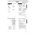
[Adjustment Method] 1) Short-circuit between pin 5 (AV ADJ) and 3 (GND) of CN261 for about 1 second to activate the RF switching position adjustment mode. 2) Check that �AF� is indicated on FL display. 3) Using the program + and � buttons, adjust to 416 ± 32µsec (6.5 ± 0.5H). 4) Press the PAUSE button. 5) The set goes to the AF switching position adjustment mode.
2-4. VIDEO SYSTEM CHECKS For the video system checks, follow the checking procedures given below as a rule. The color bar video signal supplied from the pattern generator is used as the video input signal for the video system adjustment of the recording mode. Check that the signal satisfies the specified value designated in the �Check of input signal� (Fig. 6-2-2) Unless otherwise specified, set the switches to the following positions. � INPUT SELECT switch ................................................. LINE 1 � TAPE SPEED switch ............................................................ SP [Checking Sequence] 1) X�tal OSC Check 2) SYNC AGC Check 3) White clip/Dark clip Check 4) Recording Y Level Check 5) Recording Chroma Level Check 6) Playback Level Check 2-4-1. Mode X�tal OSC Check (MA-316 Board) Playback Alignment tape: SP Color bar portion Q211 Emitter Oscilloscope and Frequency counter 4,433,619 ± 96Hz
CH1
Approx. 1Vp-p Approx. 5Vp-p V Enlargement Vertical sync. signal
CH2
CH1
CH2 (CN261 PIN 2 (RF SWP)) (RP-231)
6.5 ± 0.5H (416 ± 32 µsec)
Signal Measurement point Measuring instrument Specified value
Fig. 6-2-3
6) 7) 8) 9) Check that �AH� is indicated on FL display. Using the program + and � buttons, minimize a chipped portion. At this time, confirm that a noisy sound is not heard. Press the PAUSE button. Press the EJECT button.
CH2 RF SWP (CN261 PIN 2) (RP-231)
Note: A frequency counter should be connected through a buffer amplifier (oscilloscope, etc.) having a high impedance and a low capacitance. [Check Method] 1) Check that the oscillation frequency satisfies the specified value and that the oscillation voltage is 500 ± 200mVp-p.
500 ± 200mVp-p
CH1 OK HF ADJ (CN341 PIN 1) (RP-231) NG
4,443,619 ± 96Hz
Fig. 6-2-5
Should be minimized RF signal dropout
Fig. 6-2-4
6-3
|
|
|
> |
|