|
|
|
Who's Online
There currently are 6043 guests online. |
|
Categories
|
|
Information
|
|
Featured Product
|
|
|
 |
|
|
There are currently no product reviews.
 ;
This manual is complete and of high quality. I am very pleased with the purchase.
;
Another excellent buy! A fully readable PDF archive. Good prints!!
;
It is wonderful done!!! a great job in scanning the manual. Superior quality in all the electric scheme. Very understandable and net!!! Thank you!
 ;
muy buen manual por lo completo de este algunos esquemas estan muy divididos lo que hace algo dificil el seguimiento.
;
very good manual, with detail and clarity in esquematic diagrams and waveforms .
2-4-2.
Hi-Fi Switching Position Adjustment (MA-342 Board) [Adjustment Purpose] To adjust the link of the A-ch and B-ch of the tape playback outputs. To make the unit compatible with other tapes and units. If this specification is not satisfied, the link will appear on the screen and the screen will be disrupted, etc. Mode Signal Measurement point Measuring instrument Adjusting element Specified value Playback Alignment tape: SP color bar portion CH1: CN270 Pin 1 (HF ADJ) CH2: CN270 Pin 3 (RF SWP) Oscilloscope Remote Commander CH +/� B=minimize
2-4-3. Normal Audio System Adjustment � Make adjustment in the SP mode unless otherwise specified. Use a normal VHS cassette for an adjustment tape. � Set AUDIO MONITOR to normal. 2-4-4. ACE Head Adjustment Refer to the VHS mechanical adjustment manual MECHANISM) (9-921-647-11).
(S
2-4-5. E-E Output Level Check [Adjustment purpose] Confirm that the output level adjust the reference input is within the specification. Mode Signal Measurement point Measuring instrument Specified value E-E 400 Hz, �7.5 dBs CJ561 L/R Audio level meter �7.5 ± 2 dBs
[Adjustment Method] 1) Check that �A H� is indicated on FL display. 2) Adjust so that part B becomes minimized at CH +/�. 3) Write data EEPROM by pressing PAUSE button. 4) Check that �A H� indicator turns off. 5) If �A H� indicator is still on, restart RF switching position Adjustment from the beginning.
B
[Check Method] 1) Input signal of 400 Hz and �7.5 dBs to the CJ561 L/R. 2) Check that the audio output level is �7.5 ± 2 dBs. 2-4-6. Frequency Response Check [Adjustment purpose] Confirm that the frequency characteristic is within the specification. Mode REC and PB (SP mode) Signal Measurement point Measuring instrument Specified value 400 Hz, �27.5 dBs 7 kHz, �27.5 dBs CJ561 L/R Audio level meter 0 ± 3 dB
CH1 HFADJ CH2 RF SWP
Note: Tape path adjustment must have been completed.
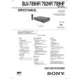
Fig. 6-2-5
[Confirmation Method] 1) Supply a signal of 400 Hz, �27.5 dBs to CJ561 L/R. 2) Connect the audio level meter to CJ561 L/R. 3) Adjust the attenuator so that the audio level meter will indicate �27.5 dBs. 4) Make recording in the SP mode. 5) Set an audio line input signal to 7 kHz and make recording. 6) Playback a recorded portion, and measure output levels at 400 Hz and 7 kHz. 7) Confirm that the 7 kHz playback output level within a range of the 400 Hz playback output level 0 ± 3 dB.
6-4
|
|
|
> |
|