|
|
|
Who's Online
There currently are 6043 guests online. |
|
Categories
|
|
Information
|
|
Featured Product
|
|
|
 |
|
|
There are currently no product reviews.
 ;
My first manual from Owner-Manuals.com but not the last! I am very satisfied with the easy ordering and promt delivery of a manual I did not find anywhere else.
 ;
This manual is very helpfull to use the Power Supply. All technical information has been available.
For service use the circuit diagrams are very good.
Thanks .
;
Very comprehensive document which is a must-have for any Satellit 2100 owner whose set up is somewhat intricate. Due to the bad quality of the pictures that are rather dark and a bit blurred I gave 4-star feedback.
;
The manual was missing 2 pages but when I presented the problem to the company they made every attempt to get the 2 pages to me, when they couldn't they refunded my money. A very pleasing and easy transaction. The manual they provided was the original, it was concise and to the point. I plan to do business with this company again when should the need arise.
;
The owners manual is very good. all my how to questions were answered in detail.
2.
HOW TO REPLACE A ROTARY UPPER DRUM (777HF, 778HFMODEL)
See below for note.
2-1.
1) 2) 3)
HOW TO REMOVE A ROTARY UPPER DRUM
2-2.
1) 2)
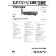
Remove screw 1 (+P3 � 8) and remove the ground shaft assembly 2. (Refer to Fig. 4.) Remove soldering which is marked by arrow and remove the rotary upper drum board completely. Remove two screws 3 (PSW3 � 8) and remove the rotary upper drum in the direction of A. (Refer to Fig. 5.) If removal is difficult, remove it while rotating it slowly.
HOW TO ATTACH A NEW ROTARY UPPER DRUM
3)
Pay attention so that finger print or like must not be put when inserting a new upper drum into lower drum. Align mark of the rotary upper drum board with the mark of the rotary transformer board so that the screw hole on the upper drum and that on the lower drum are aligned. (Refer to Fig. 5.) If attaching is difficult, attach a upper drum while rotating it slowly.
Note: If removal is difficult, check again if soldering is removed completely.
2 Ground shaft assembly 1 Screw (+P3 � 8)
Note: Pay attention not to damage the video heads. Confirm that the upper drum is inserted completely. 4) 5) Tighten the two screws 3 (PSW3 � 8). (Refer to Fig. 5.) Fix the earth shaft 2 by tightening the screw 1 (+P3 � 8) so that protrusion at the tip of the earth shaft contacts the center of the drum shaft.
Soldering Soldering
4 Plate spring
Drum when viewed from the top
Note: When attaching the ground shaft assembly 2, never give force to the plate spring 4.
3 PSW3 � 8
Upper drum assembly DZR-45-R (8-848-576-02) (777HF, 778HF)
A
Align the two arrow marks.
Fig. 4
Lower drum assembly DZL-51B/J-RP (8-848-666-11) (777HF, 778HF)
Fig. 5
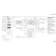
NOTE : There are two types of drum assembly built in models except SLV-788HF (DZH-94A/Z-RP only). [Discrimination]
UPPER DRUM ASSEMBLY DZR-45-R (777HF, 778HF) (8-848-576-02)
DRUM ASSEMBLY DZH-94A/Z-RP (8-839-044-02)
�Top View�
�Top View�
There are two printed circuit boards on the top.
There is no printed circuit board.
Note: It cannot be divided to two parts, the upper and the lower drum assemblies.
�7�
|
|
|
> |
|