|
|
|
Who's Online
There currently are 5980 guests and
1 member online. |
|
Categories
|
|
Information
|
|
Featured Product
|
|
|
 |
|
|
There are currently no product reviews.
 ;
Good copy and great customer service! There was some confusion with my order and it was resolved promptly!
;
Having bought a pre-owned Sony FM stereo tuner through eBay, it came without any manuals. It soon became clear that to get the best from this excellent tuner I needed a decent manual because much of the operation was not intuitive to a newboy to hi fi like me. I managed to download the official Sony multi-lingual manual from Owner-Manuals.com with no problem at all - a really quick and easy service. I'm very glad I did because I found out all the operations of the tuner and was then able to not only set it up quickly but also to get much more from it that poke-and-hope trialling would ever achieve. In my book $4.99 very well spent.
;
This manual is immaculate in it's accuracy. Everything is written very clearly and easy to understand. Written by a professional who wants to convey a clear and easy to understand message!!
;
This Manual (as downloaded) is both informative and comprehensive and has proved to be extremely useful. thoroughly recommended.
;
everything is ok, thank you very much! Product is good, no problems with download!
2.
HOW TO REPLACE A ROTARY UPPER DRUM (777HF, 778HFMODEL)
See below for note.
2-1.
1) 2) 3)
HOW TO REMOVE A ROTARY UPPER DRUM
2-2.
1) 2)
Remove screw 1 (+P3 � 8) and remove the ground shaft assembly 2. (Refer to Fig. 4.) Remove soldering which is marked by arrow and remove the rotary upper drum board completely. Remove two screws 3 (PSW3 � 8) and remove the rotary upper drum in the direction of A. (Refer to Fig. 5.) If removal is difficult, remove it while rotating it slowly.
HOW TO ATTACH A NEW ROTARY UPPER DRUM
3)
Pay attention so that finger print or like must not be put when inserting a new upper drum into lower drum. Align mark of the rotary upper drum board with the mark of the rotary transformer board so that the screw hole on the upper drum and that on the lower drum are aligned. (Refer to Fig. 5.) If attaching is difficult, attach a upper drum while rotating it slowly.
Note: If removal is difficult, check again if soldering is removed completely.
2 Ground shaft assembly 1 Screw (+P3 � 8)
Note: Pay attention not to damage the video heads. Confirm that the upper drum is inserted completely. 4) 5) Tighten the two screws 3 (PSW3 � 8). (Refer to Fig. 5.) Fix the earth shaft 2 by tightening the screw 1 (+P3 � 8) so that protrusion at the tip of the earth shaft contacts the center of the drum shaft.
Soldering Soldering
4 Plate spring
Drum when viewed from the top
Note: When attaching the ground shaft assembly 2, never give force to the plate spring 4.
3 PSW3 � 8
Upper drum assembly DZR-45-R (8-848-576-02) (777HF, 778HF)
A
Align the two arrow marks.
Fig. 4
Lower drum assembly DZL-51B/J-RP (8-848-666-11) (777HF, 778HF)
Fig. 5
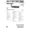
NOTE : There are two types of drum assembly built in models except SLV-788HF (DZH-94A/Z-RP only). [Discrimination]
UPPER DRUM ASSEMBLY DZR-45-R (777HF, 778HF) (8-848-576-02)
DRUM ASSEMBLY DZH-94A/Z-RP (8-839-044-02)
�Top View�
�Top View�
There are two printed circuit boards on the top.
There is no printed circuit board.
Note: It cannot be divided to two parts, the upper and the lower drum assemblies.
�7�
|
|
|
> |
|