|
|
|
Who's Online
There currently are 5522 guests online. |
|
Categories
|
|
Information
|
|
Featured Product
|
|
|
 |
|
|
There are currently no product reviews.
 ;
This is exactly the service manual I needed.
Complete with all schematics, partslists, PCB layouts and alignment instructions.
This manual covers both the T-4970 en T-488F Onkyo tuner.
 ;
IF PRINTED CIRQUIT BOARD WIRING VIEW WAS ONE TONE LIGHTER, THEN 5 STAR RANK HAS TO BE MY CHOISE.
;
Very usefull, good quality drawings !
Muito útil encontrei todas as informações necessárias.
;
Wanting to repair a neighbours tape recorder I needed the necessary information, it makes it easier. Although the service manual is described as "Language : English" To my dismay I found that it is entirely written in German, a language I do not understand. At least I now have the schematics which will help of sorts. I may not use this service again due to the laguage difficulty after all when it states English you do not expect it to be entirely in another language.
;
GOOD SERVICE MANUAL.I ALWAYS BUY THERE IF I FIND WHAT I AM LOKING
SAFETY CHECK-OUT
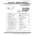
After correcting the original service problem, perform the following safety checks before releasing the set to the customer: 1. Check the area of your repair for unsoldered or poorly-soldered connections. Check the entire board surface for solder splashes and bridges. 2. Check the interboard wiring to ensure that no wires are �pinched� or contact high-wattage resistors. 3. Check that all control knobs, shields, covers, ground straps, and mounting hardware have been replaced. Be absolutely certain that you have replaced all the insulators. 4. Look for unauthorized replacement parts, particularly transistors, that were installed during a previous repair. Point them out to the customer and recommend their replacement. 5. Look for parts which, though functioning, show obvious signs of deterioration. Point them out to the customer and recommend their replacement. 6. Check the line cords for cracks and abrasion. Recommend the replacement of any such line cord to the customer. 7. Check the B+ and HV to see if they are specified values. Make sure your instruments are accurate; be suspicious of your HV meter if sets always have low HV. 8. Check the antenna terminals, metal trim, �metallized� knobs, screws, and all other exposed metal parts for AC Leakage. Check leakage as described right. LEAKAGE TEST The AC leakage from any exposed metal part to earth ground and from all exposed metal parts to any exposed metal part having a return to chassis, must not exceed 0.5 mA (500 microamperes). Leakage current can be measured by any one of three methods. 1. A commercial leakage tester, such as the Simpson 229 or RCA WT540A. Follow the manufacturers� instructions to use these instruments. 2. A battery-operated AC milliammeter. The Data Precision 245 digital multimeter is suitable for this job. 3. Measuring the voltage drop across a resistor by means of a VOM or battery-operated AC voltmeter. The �limit� indication is 0.75 V, so analog meters must have an accurate low-voltage scale. The Simpson 250 and Sanwa SH-63Trd are examples of a passive VOMs that are suitable. Nearly all battery operated digital multimeters that have a 2 V AC range are suitable. (See Fig. A)
To Exposed Metal Parts on Set
0.15 µF
1.5 k�
AC Voltmeter (0.75 V)
Earth Ground
Fig. A. Using an AC voltmeter to check AC leakage.
SDM-S71(E)
2
 $4.99 SDMS71 SONY
Owner's Manual Complete owner's manual in digital format. The manual will be available for download as PDF file aft…
|
|
|
> |
|