|
|
|
Who's Online
There currently are 5811 guests online. |
|
Categories
|
|
Information
|
|
Featured Product
|
|
|
 |
|
|
There are currently no product reviews.
 ;
Exactly the JVC service manual and schematics that I was looking for - delivered just hours after order. Will do business again!
;
This is a fantastic site, ad I have been a returning satisfied cusumer!
Thanx for a great sevice!
;
Je suis audiophile belge, électronicien et créateur d'enceintes acoustiques.
J'ai apprécié la qualité des documents fournis. Ils sont très lisibles, ils peuvent être agrandis sans problème et ils sont complets. Pour moi, c'est parfait. Pour cette qualité, je suis d'accord de payer. Et le système de paiement et d'envoi est simple. Merci, continuez comme cela.
Frédéric
;
The cover page was a little scary, very dark but readable. The remainder of the document was better copy and easily readable. Why would I give 5 Stars? (1) PRICE, (2) AUTHENTICITY, It was the real deal, filled with service information, including the specific information I required. (3) PRIVACY, I didn't start to get slammed with spam. (4) EASY TRANSACTION. Painless. (5) COMPLETE, I have found several manuals here, that I could find nowhere else. (6) I will be a repeat customer!
;
Well done!!! I found what I need to have, indeed!
Furthermore, due to my hobby is repairing vintage equipments, I added this web site in my desk toolbar because I have in mind to search further service manuals. Thanks a lot www.owner-manuals.com !
Regards, Maurizio
SECTION 1 GENERAL
TABLE OF CONTENTS
This section is extracted from instruction manual.
Specifications ........................................................................... 1
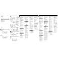
LOCATION AND FUNCTION OF CONTROLS
1. GENERAL
Location and Function of Controls .................................... 2
2. DISASSEMBLY
2-1. Cabinet (Lower) .......................................................... 3 2-2. Front panel .................................................................. 3 2-3. Main Board ................................................................. 4
3. DIAGRAMS
3-1. Printed Wiring Boards ................................................ 5 3-2. Schematic Diagram ..................................................... 7
4. EXPLODED VIEW ................................................. 9 5. ELECTRICAL PARTS LIST .................................... 10
Flexible Circuit Board Repairing � Keep the temperature of the soldering iron around 270°C during repairing. � Do not touch the soldering iron on the same conductor of the circuit board (within 3 times). � Be careful not to apply force on the conductor when soldering or unsoldering. Notes on chip component replacement � Never reuse a disconnected chip component. � Notice that the minus side of a tantalum capacitor may be damaged by heat.
�2�
 $4.99 SBD30 SONY
Owner's Manual Complete owner's manual in digital format. The manual will be available for download as PDF file aft…
|
|
|
> |
|