|
|
|
Who's Online
There currently are 6043 guests online. |
|
Categories
|
|
Information
|
|
Featured Product
|
|
|
 |
|
|
There are currently no product reviews.
 ;
Good quality, all schematics of few of models. There is also short form of user manual and regulation manual.
;
Perfect copy of the service manual. you can enlarge every page, and it comes up
with all details.
;
It´s very very nice manual with all, what i need. Original in good quality. Very fast business. Very much thanks...
;
Purchased the manual that I was looking for at a great price and could download it easily.. Great service experience and for future purchases I plan to use the site.
Thank you very much
;
Exactly what was needed to assess the product - excellent value and great service
TABLE OF CONTENTS TEST MODE ······································································ 3 1. GENERAL ·········································································· 4 2. DISASSEMBLY
2-1. Removal Amplifier Block ··················································· 5
3. DIAGRAMS
3-1. 3-2. 3-3. 3-4. 3-5. 3-6. 3-7. 3-8. 3-9. 3-10. 3-11. 3-12. 3-13. 3-14. Circuit Boards Location ····················································· 6 Schematic Diagram �Dolby Section � ··························· 7 Printed Wiring Board �Dolby Section � ························· 9 Schematic Diagram �Display Section � ······················· 11 Printed Wiring Board �Display Section � ···················· 13 Schematic Diagram �Power Section � ························· 15 Printed Wiring Board �Power Section � ······················ 17 Schematic Diagram �Power Transformer Section � ···· 19 Printed Wiring Board �Power Transformer Section � ·· 21 Printed Wiring Board �Main Section � ························ 23 Schematic Diagram�Main Section (1/2) � ··················· 25 Schematic Diagram �Main Section (2/2) � ················· 27 IC Pin Function ································································ 29 IC Block Diagrams ··························································· 30
4. EXPLODED VIEWS
4-1. 4-2. 4-3. 4-4. 4-5. System (L) Assy ······························································· 32 System (R) Assy ······························································· 33 Amplifier Section ····························································· 34 Rear Speaker Section ························································ 35 Center Speaker Section ···················································· 36
5. ELECTRICAL PARTS LIST ······································· 37
SAFETY CHECK-OUT
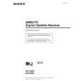
After correcting the original service problem, perform the following safety checks before releasing the set to the customer: Check the antenna terminals, metal trim, �metallized� knobs, screws, and all other exposed metal parts for AC leakage. Check leakage as described below. 3. Measuring the voltage drop across a resistor by means of a VOM or battery-operated AC voltmeter. The �limit� indication is 0.75 V, so analog meters must have an accurate low-voltage scale. The Simpson 250 and Sanwa SH-63Trd are examples of a passive VOM that is suitable. Nearly all battery operated digital multimeters that have a 2V AC range are suitable. (See Fig. A)
LEAKAGE
The AC leakage from any exposed metal part to earth ground and from all exposed metal parts to any exposed metal part having a return to chassis, must not exceed 0.5 mA (500 microampers). Leakage current can be measured by any one of three methods. 1. A commercial leakage tester, such as the Simpson 229 or RCA WT-540A. Follow the manufacturers� instructions to use these instruments. A battery-operated AC milliammeter. The Data Precision 245 digital multimeter is suitable for this job.
To Exposed Metal Parts on Set
0.15µF
1.5k�
AC voltmeter (0.75V)
2.
Earth Ground Fig. A. Using an AC voltmeter to check AC leakage.
SAFETY-RELATED COMPONENT WARNING!! COMPONENTS IDENTIFIED BY MARK ! OR DOTTED LINE WITH MARK ! ON THE SCHEMATIC DIAGRAMS AND IN THE PARTS LIST ARE CRITICAL TO SAFE OPERATION. REPLACE THESE COMPONENTS WITH SONY PARTS WHOSE PART NUMBERS APPEAR AS SHOWN IN THIS MANUAL OR IN SUPPLEMENTS PUBLISHED BY SONY. ATTENTION AU COMPOSANT AYANT RAPPORT � LA S�CURIT�! LES COMPOSANTS IDENTIF�S PAR UNE MARQUE ! SUR LES DIAGRAMMES SCH�MATIQUES ET LA LISTE DES PI�CES SONT CRITIQUES POUR LA S�CURIT� DE FONCTIONNEMENT. NE REMPLACER CES COMPOSANTS QUE PAR DES PI�SES SONY DONT LES NUM�ROS SONT DONN�S DANS CE MANUEL OU DANS LES SUPP�MENTS PUBLI�S PAR SONY.
�2�
 $4.99 SAVA29 SONY
Owner's Manual Complete owner's manual in digital format. The manual will be available for download as PDF file aft…
|
|
|
> |
|