|
|
|
Who's Online
There currently are 5993 guests online. |
|
Categories
|
|
Information
|
|
Featured Product
|
|
|
 |
|
|
There are currently no product reviews.
 ;
I really like this manual and it's reliable.I found and bought easly.thank you.
;
Thank you very much. the Instruction corresponds to my expectations. Sent it in time. I don't regret that paid money.
;
Good quality. Quick service. I recommend to everyone.
;
Very good quality scan of the document. I am very pleased with what I got.
;
PDF Contains
Technical Data, Mechanical data, Detailed Circuit diagram with components value, PCB layout. Actual PCBs Print. Component List, Spare parts code list and Input output detail. It cover LBB1211, LBB1212, LBB1213, LBB1216, LBB1217.
It is the actual Service Manual for SQ10
SAT-HD100
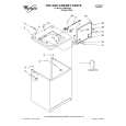
1-4. A, G & TU BOARD REMOVAL
4
5
6
7
8
9
3
2 1
Note: For board removal or replacement, detach all attached cables, and leave them attached to an existing board.
10 11
7
1 2 3
Detach the connector between the A and G Boards. Remove (2) screws (+BVTT 3 x 12) from G Board. Remove (1) screw (+BVTP 3 x 8) from G Board. Gently lift the board forward and up to remove. Remove (1) screw (M3 x 6) from the back panel holding in the tuning unit. Remove (2) hex nuts from the cable jacks. Remove (2) screws (+BVTP 3 x 8) from the back of the unit, mounting the fan assembly. Lift the assembly up and out to remove.
Remove (2) screws (M3 x 6) from the back of the unit, mounting the RF Remote Assembly. Lift the assembly up and out to remove. Remove (2) screws (+BVTP 3 x 8) from the back of the unit at the RCA jacks. Remove (2) screws (+BVTT 3 x 12) mounting the TU Board to chassis. Remove (4) screws (+BVTT 3 x 12) mounting A Board to Chassis. Gently lift the A and TU Boards simultaneously forward and up to remove. Support the weight of both boards at the connector. Once removed from the chassis, disconnect the connector shown to separate the A and TU Boards.
8
4 5 6
�8�
|
|
|
> |
|