|
|
|
Who's Online
There currently are 5863 guests online. |
|
Categories
|
|
Information
|
|
Featured Product
|
|
|
 |
|
|
There are currently no product reviews.
 ;
Good price for the manual and easy to locate on the site and download. Plus, just like the original. Thanks a lot.
;
Genuine Service Manual. Link was available in less then an hour or so. Service Manual contains assembly, PCB layout, complete circuit diagram, Components list etc
;
Great and very well scanned Service Manual, also very fast download - Recomended !
;
I'm quite impressed. I had to wait 24 hours for my manual (quite a rare one) but I got it and the quality was good. Also, from trawling the web, these prices are by far the best.
;
Manuale perfetto. Ottimo e utilissimo. Grazie a questo manuale ho potuto realmente risolvere il complesso problema della stampante.
RCD-W3
NOTE ON CHECKING POWER SUPPLY CIRCUIT
1. When check the primary part, you must remove the GND pin of the scope and soldering machine. Primary GND : C103 � terminal at power board. 2. When check the primary part, you must open the another GND(not used GND) of scope. (If another scope GND is connected to secondary GND or other system, input power line or system have some damage.) 3. When touch the primary part by hand in defected system, if you use the power line switch, remove the power cord and then check or touch. Because in general power switch is switching only one line. 4. When check the primary part, after remove power cord and dis charge the primary capacitor, and then check the system. In the normal state, the voltage of the capacitor is small (about 10V), but in the abnormal state is very high ( about 140V at 100V A.C or 300V at 220V). When discharge the capacitor, use the wattage resistor(about 100 ohm). 5. In the narrow system, Until set repaired completely, insert the power cord at the moment repeatedly and then check the waveform. 6. In the wide system, when insert the power cord, check the wave form after about 3 second. Because the wide system is the soft start method.
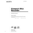
BD-R BOARD CHECK AND ADJUSTING JIGS
In case of checking or adjusting the LD power of BD-R board, the PC connection jig (J-2501-210-A) and the test program are required. This test program is distributed with the service manual.
RCD-W3 BD-R board
CD-R test connector (PN105)
PC connection jig (J-2501-210-A) PS-232C cable (D-sub 9pin) (straight type)
SW501
W D
PC connection jig Set SW501 to �D� side
CNP501
CN505
PC
7
 $4.99 RCDW3 SONY
Owner's Manual Complete owner's manual in digital format. The manual will be available for download as PDF file aft…
|
|
|
> |
|