|
|
|
Who's Online
There currently are 5487 guests online. |
|
Categories
|
|
Information
|
|
Featured Product
|
|
|
 |
|
|
There are currently no product reviews.
 ;
The Service Manual for Sansui AU-9500 was very helpfull, in complete and in good printable condition.
Thanks.
;
Dear Sir,
Document is original service document of sharp. I had a problem with the door contacts. Fuses where blown. With the manual in a few minuts is was clear what the problem was.
Manual was of great help.
With kind regards,
Martie Verhoeven
The Netherlands.
 ;
The scan is clear and well readable with very few weaker spots, usually on black background with white letters, but with enough zoom those spots can be read.
Printout is clear, the manual is complete and has all pages scanned.
I would give 5 stars, except that it is not in color, and the schematic and PCB pages are scanned on multiple pages. The document is locked (except printing) so the pages can not be extracted to compose them together for printing on the large plotter
It is worth the price tag.
;
let's say first that i do not need to have a credit for my opinion, i am a retired sparkie and i voluteerd to fix an electronic device for a local "Youthgroup",as no diagram was present i checked the "net" and gambled on this site and paying some fee via PayPall, i was gladly surprised that the manual arrived as was stated, GOOD SHOW, and best wishes, John
;
I had been looking for a Manual for my CS2150 for quite a while -- in fact I had just about given up. I saw this site and decided to download the Manual. When I Received it by Email I was really pleased with what I got, with the result that My Kenwood 'Scope is now 100% repaired and working well. As an AV Serviceman, you need a good 'scope, and thanks to this site, and the Service Manual, I have been able to repair it. The Manual was a copy of the Factory Original and the copy was very clear, especially in the area of the Circuit Schematics, where You really need to be sure of what You are looking at.
2-2-6. Adjustment for the Power Board When the Panel is Replaced
2-3-2. Notes
(1) Without any special specification, the Module should be at the condition of preliminaries more than 10 minutes before adjusting. . Service signal : 100% Full White signal . Service DC voltage : Vcc : 5 V, Va : 65 V, Vs : 190 V . DC/DC Pack voltage : Vsetup : 220 V, Vscw : 115 V, _Ve : _35 V, _Vy : _75 V . Preliminaries environment : Temp (25 ± 5°C), Relative humidity (65 ± 10%) (2) Module should get the Aging for the equilibrium after finish the assembling. Aging condition is shown below. . Service signal : 100% Full White, Red, Green, Blue pattern signal (Service time of each pattern : within 5 minutes/cycle) . Service DC voltage : Match the voltage with the set up voltage in the first adjustment. . Aging time : More than 4 Hrs . Aging environment : Temp (60 ± 2°C), relative humidity-Less than 75% (3) Module adjustment should be followed by below sequence. . Setting up the initial voltage and adjusting the voltage wave form of Vsetup . Measuring the Margin of Vs voltage and deciding the voltage . Adjusting and checking the voltage of DC/DC pack (Vsetup, Vscw, _Ve, _Vy) . Adjusting the voltage wave form of Vset-down . Measuring the voltage margin of Vset-up and deciding the voltage . Adjusting the wave form of final voltage But, these items above can be changed by the consideration of mass production. (4) Without any special specification, you should adjust the Module in the environment of Temp (25 ± 5°C) and Relative humidity (65 ± 10%) c If you let the still image more than 10 minutes (especially The Digital pattern or Cross Hatch Pattern which has clear gradation), after image can be presented in the black level part of screen.
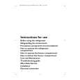
The label shown in the picture above is stuck on the upper right position at the back side of the panel, on which the Va and Vs voltages for each panel are described.
Vs adjusting VR Va adjusting VR
The Vs and Va adjusting VRs are located at around the center part of the power board as shown in the picture. After replacing the panel, adjust each VR so that it becomes the voltage described in the above label (± 0.5 V). Voltage measurement is performed between pin 1 of CN807 and chassis GND for Vs, and between pin 6 of CN807 and pin 10 of CN806 for Va.
2-3. Adjustment for Panel
2-3-1. Application Object
This standard is applied to the PDP42V5#### PDP Module which is manufactured by the manufacturing team of PDP promotion department or elsewhere.
PFM-42V1/42V1A/42V1E/42V1P
2-3
|
|
|
> |
|