|
|
|
Who's Online
There currently are 5872 guests online. |
|
Categories
|
|
Information
|
|
Featured Product
|
|
|
 |
|
|
There are currently no product reviews.
 ;
I am satisfied with the service. And if need another manual, i will definitely buy from this site. Keep up the good work.
;
have download a number of manuals todate , most are excellant, one or two sometimes a little difficult to read but a least avaialable, great site .
Brad.
;
Excellent had everything I wanted, very happy with purchase
 ;
This service is relatively cheap, document is fast available, schematic is readable.
Thanks.
;
So far I´m a satisfied customer. I have only downloaded "TECHNICS SX-KN470 Service Manual" maybe I will use it later.
Best regards
Peter
PCM-M1
3-2. MECHANICAL ADJUSTMENTS
Tape pass adjustment
Note: Be sure to perform the tape pass adjustment when rotary drum is replaced. Preparation: Oscilloscope CH-1: AC 100 mV/DIV CH-2: DC 2 V/DIV TRIG: CH-2
14. Move down the TG1 guide (by turning it clockwise), and confirm that the RF waveform loses parallel shape, then return the SG1 guide to original position. When the original waveshape cannot be restored (Fig. 8), repeat steps 5 to 8. (note) Do not adjust the SG1 and TG1 guides at the same time.They must be testified and adjusted independently.) Be sure to complete adjustment of either one of the guides, then start adjustment on the other guide. 15. Confirm that the waveform during the FWD mode is obtained in the following modes. Confirm also that the waveform in the FF/REW mode conforms to the waveform shown in Fig. 9. FWD � STOP � FWD � CUE � FWD � REV � FWD � STOP � FF � FWD � STOP � REW � FWD � STOP � EJECT � FWD
� Confirmation of speed [Capstan FG] 1. Connect a frequency counter to TP508 (CFG). 2. 3. 4. 5. Establish a test mode. Select and set the test mode code 40. Insert a test tape TY-30B. Establish the � 0.5 FWD then � 1 FWD modes by pressing the VOLUME + key and take reading of frequency counter respectively. Mode � 0.5FWD � 1FWD Frequency 311Hz ± 5Hz 622Hz ± 5Hz
1. 2. 3. 4. 5. 6.
Connect CH-1 of an oscilloscope to TP524 (RF) and CH-2 to TP525 (SWP). Establish a test mode. Select and set the test mode code 40 and speed code 1 using the VOLUME + (up) key. (� 1 FWD) Insert a test tape TY-7915. Select and set the test mode code 42. Adjust the phase difference (T) between the SWP signal and the RF signal using the VOLUME + (up) and the VOLUME � (down) keys until the specifications as shown is satisfied.
1. 2. 3. 4. 5. 6.
Connect an oscilloscope CH-1 to TP524 (RF) and CH-2 to TP525 (SWP). Insert a test tape TY-7915 and find the center of the tape. Establish the test mode. Select and set the test mode code 42. Decrease the SG1 guide (by rotating it clockwise), and remove a tape (Fig. 1). Move down the TG1 guide (by turning it clockwise), remove a tape (Fig. 2) and turn it counter-clockwise until the right side edge of the RF waveform becomes square as shown (Fig. 3). Turn the SG1 guide counter-clockwise until the left side edge of the RF waveform becomes square as shown (Fig. 4). Notice that the lower flange of the stationary guide does not contact with tape. Confirm also that tape runs along with the upper flange of the SG1 and TG1 guides.
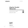
[Drum FG] 1. Connect a frequency counter to TP507 (DFG). 2. 3. 4. 5. � Confirmation of torque Preparation: Remove the cassette lid from the holder. [� 1 FWD mode] 1. Establish a test mode. 2. Select and set a test mode code 40. 3. Insert a torque meter TW-7131. 4. 5. Establish the � 1 FWD mode by pressing the VOLUME + key. Observe and confirm the torque meter reading. FWD takeup torque: 5 to 9 g�cm FWD back tension: 3 to 6.5 g�cm Establish a test mode. Select and set the test mode code 40. Insert a test tape TY-30B. Establish the � 0.5 FWD then � 1 FWD modes by pressing the VOLUME + key and take reading of frequency counter respectively. Mode � 0.5FWD � 1FWD Frequency 400Hz ± 1Hz 800Hz ± 1Hz Note: The default adjustment value for each specific drum has already been printed on the bar code label as shown. When you replace the drum with the new replacement drum, peel off the old bar code label from the machine and attach the new bar code label that is packed with the new replacement drum, to the machine. Then perform the record current adjustment.
Holder (cassette)assy Barcode lavel
7.
T=1083.5µsec ± 30µsec 7. Press the LIGHT button to save the data into EEPROM
(Fig-5)
8.
Adjust the lower flange of the stationary guide. Adjust height of the stationary guide until the lower flange contacts the tape during tape run in the PLAY mode. Tape must not show any curls.
� Record current adjustment
3-3. ELECTRICAL ADJUSTMENTS
� Voltage check 1. Establish a test mode. 2. 3. Select and set the test mode code 40. Measure DC voltage at the respective test points using VOM and confirm that the DC voltages satisfy the specifications. Test point REG3.5V (TP602) � 3.5V (TP605) MIC L (TP101) MIC R (TP201) Specifications 3.5V � 3.5V 1.9V ± 0.3V 1.9V ± 0.3V
9.
Perform the switching pulse adjustment. (Refer to 3-3. ELECTRICAL ADJUSTMENT) (Fig. 5) 1083±25µsec. [� 1 REV mode] 1. 2. 3. Establish a test mode. Select and set a test mode code 40. Insert a torque meter TW-7131. Establish the � 1 REV mode by pressing the VOLUME � key. Observe and confirm the torque meter reading. REV takeup torque: 5.5 to 8.5 g�cm REV back tension: 11.5 to 17 g�cm
10. Select and set the test mode code 02. 11. Observe the RF waveform and confirm that the waveform increases and decreases its amplitude while maintaining it parallel waveform. (Fig. 6) 12. Repeat the STOP, UNLOAD and FWD modes, and confirm that the RF waveform follows step 11. When the RF waveform loses parallel shape, repeat steps 5 to 8. 13. Move down the SG1 guide (by turning it clockwise), and confirm that the RF waveform loses parallel shape, then return the SG1 guide to original position. When the original waveshape cannot be restored (Fig. 7), repeat steps 5 to 8.
4. 5.
� Confirmation of T-reel lock 1. 2. 3. 4. Enter the test mode. Set the test mode code to 32 using the MODE key. Then press the ENTER key. Find the tape of a 120-minute tape. Insert the tape to the machine. Press the STOP key. Confirm that any number of either 0, 1, 2, 3 or 4 appears in the display window when the EJECT key is pressed. If a number of 5 or higher appears, replace the Limiter (F reel) Assy (X-3373-741-1) and check the T-reel lock again.
� Switching pulse (SWP) adjustment Note: Be sure to perform the tape pass adjustment when rotary drum is replaced. Preparation: Oscilloscope Frequency band width: 100 MHz or more CH-1: AC 100 mV/DIV CH-2: AC 2 V/DIV 0.2 msec/DIV TRIG:CH-2
Default adjustment value of the adjustment target code-3 Default adjustment value of the adjustment target code-2 Default adjustment value of the adjustment target code-1 Default adjustment value of the adjustment target code-0 1. 2. 3. 4. 5. Enter the test mode. Set the test mode code to 43 using the MODE key. Then press the ENTER key. Confirm to see that the adjustment target code which is shown on the test mode display, is 0. When you need to change the adjustment target code, press the RESET/+ key to select the desired adjustment target code No. Adjust the record current to the default adjustment value shown on the bar code label by pressing the VOLUME (+) or (-) key. Then press the LIGHT key. Repeat the steps 3 and 4 until all adjustment items from the adjustment target code-0 to -3 are complete.
� 23 �
� 24 �
� 25 �
 $4.99 PCMM1 SONY
Owner's Manual Complete owner's manual in digital format. The manual will be available for download as PDF file aft…
|
|
|
> |
|