|
|
|
Who's Online
There currently are 5946 guests online. |
|
Categories
|
|
Information
|
|
Featured Product
|
|
|
 |
|
|
There are currently no product reviews.
 ;
Excellent high quality schematics brought my old Heidelberg back to life. Fast download at a reasonable price. Thanks.
;
This document is just what I was looking for, it´s very useful, it contains adjustment procedures for the final stage of the power amp and also
has a complete wiring diagram and description of the main semiconductors used in the design.
;
Dear Sirs,
Thank you for the fast support, the manual does provide all necessary information to repair the radio. All schematics are in a good quality for reading.
The manual fits 100% to my requirements as a technican.
Kind regards Thomas
;
the big video recorder format s-vhs many features delicate in loading system of the cassette. Such machines are no longer manufactured, it would be too expensive.
 ;
THIS MANUAL IS VERY GOOD AND VERY CLEAR
PLEASE NOTE IT DOES NOT CONTAIN THE SETUP INFORMATION TO ALIGHN THE GEARS IN THE CD MECH IT DOES SHOW ALL THE PARTS AND THEIR LOCATIONS .
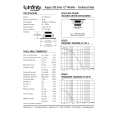
MZ-G750/G750DPC/R700/R700DPC/R700PC
� Modified Data Writing Method (version 1.000) 1. Select the manual mode of the test mode, and set item number 023 (see page 13).
This set LCD display
12. Adjust with the [VOL+] key (adjusted value up) or [VOL--] key (adjusted value down) so that the adjusted value becomes 8B.
This set LCD display
Patch
00: Adjusted value
00
0 23
0D5E8B
8B: Adjusted value
0 23
2. Press the [VOL+] key once to change the adjusted value to 01. 3. Press the [T MARK] key for several seconds (about 3 seconds) to activate the patch data write mode. (The following display will appear where 00 is blinking)
This set LCD display
13. Press the X key. (0D5E is blinking) 14. Press the [VOL+] key once to change the blinking portion to 0D5F.
This set LCD display
0D5800
00: Adjusted value
0 23
0D5F00
00: Adjusted value
0 23
4. Adjust with the [VOL+] key (adjusted value up) or [VOL--] key (adjusted value down) so that the adjusted value becomes 1E.
This set LCD display
15. Press the x key. (00 is blinking) 16. Adjust with the [VOL+] key (adjusted value up) or [VOL--] key (adjusted value down) so that the adjusted value becomes 20.
This set LCD display
0D581E
1E: Adjusted value
0 23
0D5F20
5. Press the X key. (0D58 is blinking)
This set LCD display 20: Adjusted value
0 23
0D581E
1E: Adjusted value
0 23
17. Press the X key. (0D5F is blinking) 18. Press the [VOL+] key once to change the blinking portion to 0D60.
This set LCD display
6. Press the [VOL+] key once to change the blinking portion to 0D59.
This set LCD display
0D6000
00: Adjusted value
0 23
0D5900
00: Adjusted value
0 23
19. Press the x key. (00 is blinking) 20. Adjust with the [VOL+] key (adjusted value up) or [VOL--] key (adjusted value down) so that the adjusted value becomes 08.
This set LCD display
7. Press the x key. (00 is blinking) 8. Adjust with the [VOL+] key (adjusted value up) or [VOL--] key (adjusted value down) so that the adjusted value becomes B2.
This set LCD display
0D6008
08: Adjusted value
0 23
0D59B2
B2: Adjusted value
0 23
21. Press the X key. (0D60 is blinking) 22. Press the [VOL+] key once to change the blinking portion to 0D61.
This set LCD display
9. Press the X key. (0D59 is blinking) 10. Press the [VOL+] key once to change the blinking portion to 0D5E.
This set LCD display
0D6100
00: Adjusted value
0 23
0D5E00
00: Adjusted value
0 23
23. Press the x key. (00 is blinking) 24. Adjust with the [VOL+] key (adjusted value up) or [VOL--] key (adjusted value down) so that the adjusted value becomes A1.
11. Press the x key. (00 is blinking)
24
|
|
|
> |
|