|
|
|
Who's Online
There currently are 6008 guests online. |
|
Categories
|
|
Information
|
|
Featured Product
|
|
|
 |
|
|
There are currently no product reviews.
 ;
This manual is for the usa model only. But it is clear
, accurate and comprehensive, including board layouts and schematics.
I found it extremely useful for my mitsubishi dp-86da, but the same diagram would also work for the realistic lab5000 and hi fi 80. Thanks.
;
Great to have extra resources for Service Manuals, Now days you can really not trouble shoot efficiently without one , Wayne at IRIONS TV & ELECTRONICS REPAIR Clearwater , Fl. 33755 727-446-7955
 ;
For five bucks you can barely buy a hamburger. Or for the same five bucks you can buy a service manual. Much more useful. (and better for your health, depending on where you buy your hamburgers).
Yes, there are free manual sites out there, but if they don't have what you want, you have to pay.
And five bucks isn't much. Not for full specs, schematics and adjustment and parts replacement procedures.
My only criticism is that grayscale illustrations aren't well rendered, but I've seen worse.
Schematics and text are clear.
I'll be happy to purchase from here again.
Mike
[email protected]
;
Impressively thorough. Even the simple operators manual helped me "fix" one of the 2 CD players in the unit. This unit reads CD's from the top so they should be installed in the magazines "upside down" from typical CD players. The CD player service manual helped me unjam a stuck carriage because somebody transported the box laying down loaded with CD's. A little lens cleaning & the player now works well! Thanks for you help at a great price! Joe
;
I was skeptical at first but later found the manual to be good quality for the price. It took a couple hours to receive the email with the download link, well worth the wait. Thanks.
R818
SECTION 4 TEST MODE
Configuration of Test Mode The test mode has the configuration given below.
VOL + key x key Overall adjustment mode (Auto?) x key x key VOL � key x key B/> Adjustment key mode (Manu ?) B/> key
TP852 03
Outline � In this set, overall adjustment mode is made available by entering test mode to perform automatic adjustment of CD and MO. In the overall adjustment mode, the disc is determined whether it is CD or MO and adjustments are performed in sequence. If a fault is found, the location of the fault is displayed. Also, in servo mode, each adjustment can be automatically made. � Operation in the test mode is performed with the Remote Commander. A key having no particular description in the text, indicates a Remote Commander key.
RB801
552
(044 Start ?)
Setting the Test Mode
Servo mode 000 +, � keys Audio mode 100 +, � keys Power mode 300
To enter the test mode, two methods are available : 1. Entering method with key input. Turn on the HOLD switch on the set. While holding down the x key on the set, press the following remote commander keys in the following order : B/> t B/> t . t . t B/> t .t B/> t . t X t X 2. Entering method by shorting the test point Solder bridge the test point TAP805 (TEST) on the main board (connect IC801 pin ed to GND), and turn on the POWER.
[MAIN BOARD] (SIDE B)
4 70 65 80
R807
C565
Display when test mode is set
Displays of the LCD on the remote commander are shown in parentheses.
75
5 TP8061 61 60 55 TP811 50 45 41
S8 AV LIMITT
Servo Mode � Set the test mode, press the VOLUME � key and use the B/>
VOL
S DIGITAL S 2T
R802 R801
R
1 5 10
�
key to set the servo mode. � When the servo mode is set, use the B/> key and the . key to move the optical pick-up to the outer circumference and to the inner circumference respectively. � When entering another mode, refer to the configuration of test mode. 1. Structure of Servo Mode
Servo mode 000 x key B/> key
+, � keys
IC801
SP806 SP805
807 UME+
R804
X801
15 20 21 C805 25 30 35 40
Offset adjustment 010
SP804 R808
TAP805 (TEST)
RB802
B/> key
Test mode Short : Test mode Open : Normal mode
x key
011 to 013 *1 B/> key
Releasing the Test Mode 1. When test mode was entered with key input, turn off the POWER. 2. When test mode was entered by shorting the test point, turn off the POWER and open the solder bridge of TAP805 (TEST MODE) on the main board. Operation of Setting on Test Mode When the test mode is set, the LCD displays the following :
1
x key
Laser power adjustment 020
B/> key
x key
021 to 023 *1 B/> key
2 (See page 7.)
3
100V1. 000
F SHUF
ROM version display LCD on remote commander
*1 Repeatedly press B/> key to change the mode. (Refer to the following list for a description of each mode.)
� The cycle - the above ROM version display t All lit t All off - is repeated. (The ROM version is constantly displayed.) � When the PLAY MODE key is pressed and hold down, the display at that time is held so that display can be checked.
�6�
VOL +, � keys
 $4.99 MZE75 SONY
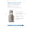
Owner's Manual Complete owner's manual in digital format. The manual will be available for download as PDF file aft…
|
|
|
> |
|