|
|
|
Who's Online
There currently are 6043 guests online. |
|
Categories
|
|
Information
|
|
Featured Product
|
|
|
 |
|
|
There are currently no product reviews.
 ;
A manual hard to find. It was very helpful to restore my device.
;
I am very grateful for this manual. Without it could not repair my receiver.
;
excellent work as always you do cheap, fast net and clean. you do an incredible service......thanks!
;
Great Job even clear than the one before!!!! god organization- I'm always very satisfied
;
I'm very happy that you all are performing an incredible good job. Furthermore what you did is very useful for all people as me that have electronics as an hobby.Thank you!!!!!
Ver 1.2 2001.12
MZ-E300
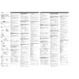
4-2-2. Operations when the TEST MODE is set When the TEST MODE is entered, the system switches to the display check mode within the TEST MODE. From this mode, the other Test modes can be accessed. When the TEST MODE is set, the LCD repeats a cycle of the following displays: Main unit LCD
4-3. TEST MODE STRUCTURE * Manual mode operation can only be performed via the remote control unit. Use the connection tool to connect the remote control unit. The display of the main unit shows �Adj�.
Test Mode (Display Check Mode) + key
F 1SHUFF AVLS BASS
u
888:88
All on
x
key
Manual Mode (Remote control only) + key Servo Mode
All off
Audio Mode
Power Mode
Microprocessor
key OP Alignment Mode Press and hold down x key
130
Remote control LCD
version display
Display segment check mode (Main unit only) Release
x
key
888
F 1SHUFF PGM u
SOUND 1 2 BASS 1 2
.
or
key Overall Adjustment Mode
All on
x
key
4-4. MANUAL MODE
All off
4-4-1. Outline of the function
008 V1.300
Microprocessor version display
The remote control display varies with the type of remote control unit used. (Example shown: RM-MC10L)
The Manual mode is designed to perform adjustments and operational checks on the set�s operation according to each individual function. Usually, no adjustments are made in this mode. However, the Manual mode is used to clear the memory before performing automatic adjustments in the Overall Adjustment mode. * Manual mode operation can only be performed via the remote control unit. Use the connection tool to connect the remote control unit. The display of the main unit shows �Adj�. 4-4-2. How to set the Manual mode 1. Set the TEST MODE and press + key to set the Manual mode. Remote control LCD display
� The current display is retained as long as either the PLAY MODE/DISPLAY key on the main unit or the PLAY MODE key on the remote control unit is pressed and held. 4-2-3. How to release the TEST MODE When method 1 was used: Turn off the power and open the solder bridge on BP801 on the main board. Note: The solder should be removed clean. The remaining solder may make a short with the chassis and other part. When method 2 or 3 was used: Turn off the power. Note: If electrical adjustment (see page 8) has not been finished completely, always start in the test mode. (The set cannot start in normal mode)
000 AAAS CC
2. When the test mode display shows �100�, �200�, �300�, �500�, �600�, �700�, �800�, or �900�, the optical pickup can be moved inside and outside of the SLED perimeter by continuously pressing the ( > N or . keys on the main unit.
7
 $4.99 MZE300 SONY
Owner's Manual Complete owner's manual in digital format. The manual will be available for download as PDF file aft…
|
|
|
> |
|