|
|
|
Who's Online
There currently are 5835 guests and
1 member online. |
|
Categories
|
|
Information
|
|
Featured Product
|
|
|
 |
|
|
There are currently no product reviews.
 ;
manual de usuario perfecto y completo de buena calidad de impresion y muy detallado ideal !
 ;
It`s full copy of a service manual from url http://www.philips.owner-manuals.com/PM3216-service-manual-PHILIPS.html
;
perfect! you just sent to me the copy in Italian witout even my specification!!!! so you are really smart cooperative and efficient. To my opinion the best place all over to get a manual of electronics!!!!
;
Well Well Well!!!! Good manual perfect for my hobby!!! As Before you have done a very well done work!!!! Thank you
;
Super nice! Good to have a manual in digital format.
8-4.
Focus Servo Circuit
As shown in Fig. 8-5., the photoelectric current output from the optical block A to D detectors is input to the RF amplifier (IC501), converted to voltage by the I-V amplifier inside, passed through the ABCD amplifier and F.E. (focus error) amplifier, and the ABCD signal is output from Pin #� (ABCD) while the focus error signal is output from Pin #§ (FE) to the DSP/digital servo (IC601). The A to D I-V amplifiers each have a gain switch for adjusting level. Using the serial data input from the system controller (IC801) via the serial bus (SBUS), initial settings of the gain is performed together with ABCD level adjustment according to the disc type each time PLAY, etc. to obtain the optimum output. To perform these, the system controller reads the ABCD level data A/D converted from the DSP/digital servo (IC601) and control the gain switch so that the data becomes the prescribed level. The input of the DSP/digital servo (IC601) is incorporated with an A/D converter, which converts the ABCD signal and the FE signal to 7-bit data at sampling frequencies of 22.05 kHz (fs/2) and 88.2 kHz (2 fs) respectively. The focus error signal is then subject to servo calculation in the DSSP (digital servo signal processor) block, converted to the 88.2 kHz PWM wave, and used to control the focus coil via the servo driver (IC551) and LPF (low pass filter). In addition to the ABCD level adjustment mentioned earlier, the A/D converted ABCD signal data is also compared with the reference level preset with the serial data from the system controller, and the FOK (focus OK) detection signal is output to the system controller via the serial bus (SBUS). The focus gain and focus bias adjustments are performed in the adjustment mode, the adjustment values are stored in the nonvolatile memory, the data is sent to the servo circuit via the serial bus (SBUS) at starting to set the focus gain and focus bias adjustment data. In the case of focus bias, data on the bias amount during adjustment is sent to the DSSP block, added to the focus error signal, and used to drive the focus coil.
� 42 �
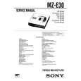 $4.99 MZE30 SONY
Service Manual Complete service manual in digital format (PDF File). Service manuals usually contains circuit diagr…
|
|
|
> |
|