|
|
|
Who's Online
There currently are 5961 guests online. |
|
Categories
|
|
Information
|
|
Featured Product
|
|
|
 |
|
|
There are currently no product reviews.
 ;
Manual was a good representation of service infomation for the EWV404. It worked well for my repair.
 ;
Great quality copy, right what I was looking for, all I need to fix my radio.
Thanks
;
I BOUGHT A PAIR OF INFINITY VINTAGE SPEAKERS THAT REQUIRED TO BE REPAIRED AND THE ELECTRONIC TECHNICIAN ASKED ME FOR THE SERVICE MANUAL.
I TRIED TO GET IT AT THE MANUFACTURER'S SITE WITH NO SUCCESS, SO I STARTED TO LOOK FOR IT IN THE WEB FOR A LONG TIME, UNTIL I FOUND THE SERVICE MANUAL IN THIS EXCELLENT SITE "OWNER'S MANUAL.COM".
NOW I HAVE MY SPEAKERS WORKING AND ENJOYING THE MUSIC I LIKE.
THANKS TO "OWNER`S MANUAL.COM" I RECOMMEND THIS SITE TO EVERYONE.
;
Very quick response. Very good and accurate print quality of the scanned document.
;
The service manual was very usable and clear enough to see the individual values of all of the components (unlike some of the service manuals I have gotten in the past from web sites similar to this one). The price was right and the information was greatly appreciated. It helped me with an otherwise very difficult repair. It was much needed and appreciated. A faster turn around on my order would be nice, but I understand the constraints on your staff's time. Thank you for your service.
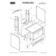
1-1-2. Precautions 1. Switch settings Adjust the switches to the following positions. 1) PLAY/CAMERA switch (PK-42 board S208) ··············································· CAMERA 2) MACRO switch (MVC-FD5 only) (LENS BLOCK MACRO lever) ······································ OFF 3) FLASH (PK-42 board S204) ··········································· OFF 4) PROGRAM AE (MVC-FD7 only) ···· Turn OFF all marks from the LCD 2. Adjustment sequence Adjust in the given order. 3. Subject 1) Set the camera and pattern box as shown in Fig. 6-1-2. 2) Color bar chart (Standard picture frame) � Adjust the picture frame as shown in Fig. 6-1-3. � Adjust camera zooming and direction until the camera output waveform on the oscilloscope shown in Fig. 6-1-3 (a) and the color picture on the LCD shown in Fig. 6-1-3 (b) have been acquired. � Maintain this setup until adjustment is complete.
3)
White pattern (Standard picture frame) Remove the color bar chart from the pattern box and adjust the camera setup until the white pattern picture frame is the same size and same position as the color bar chart (the standard picture frame).
Fig. 6-1-2
[MVC-FD7 model] Adjust direction and zoom of camera so that the picture frame is adjusted as specified by Fig. a and Fig. b. [MVC-FD5 model] Direct the camera toward the subject and place the subject with the distance (about 40cm) from camera until the specified picture frame fills the monitor display as shown in Fig. a and Fig. b. Fig. 6-1-3 4) Chart for flange back adjustment Join together a piece of white A0 size paper (1189mm � 841 mm) and a piece of black paper to make the chart shown in Fig. 6-1-4.
Note : Use a non-reflecting and non-glazing vellum paper. The size must be A0 or larger and the joint between the white and black paper must not have any undulations.
Fig. 6-1-4
6-2
 $4.99 MVCFD7 SONY
Owner's Manual Complete owner's manual in digital format. The manual will be available for download as PDF file aft…
|
|
|
> |
|