|
|
|
Who's Online
There currently are 6021 guests online. |
|
Categories
|
|
Information
|
|
Featured Product
|
|
|
 |
|
|
There are currently no product reviews.
 ;
Some of the pictures in this manual are a bit irritating. I had to dissassemble the unit and some of the screws have different threads, which is not mentioned in this manual. Also some of the drawings of the boards look different than the actual boards.
After all, the manual was very useful. I was able to recalibrate the capstan drive and it is working fine again.
 ;
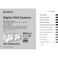
This manual is very good. 303 pages scanned in a very high resolution. My camera has bad, leaking capacitors which all of the V5000 models are suffering from these days.
There is a huge part list with all capacitors, transistors etc. in this manual which helped me a lot. Otherwise I would not have been able to buy replacement parts.
The dissassembly guide is very enormous and detailed. Unlike on the Panasonic MS1 manual I downloaded here it actually looks like the real parts look. And the screws are labeled correctly, so you shouldn't have any left after the repair. ;)
;
has all the schematics you could need,and very well laid out format also has all part numbers along with an exploded view which is helpful
;
Very nice to have! Now it is no problem to understand how it is put together.
Helps me a lot.
;
good scans, all is clear. all pages in order. recommended
MVC-CD250/CD400
1-1-4. Precaution 1. Setting the Switch Unless otherwise specified, set the switches as follows and perform adjustments.
Yellow
SETUP settings VIDEO OUT (SETUP2) ............................................... NTSC MENU settings 1. WHITE BALANCE ..................................................... AUTO 2. ISO ............................................................................... AUTO 3. IMAGE SIZE ............................ 2272 � 1704 (MVC-CD400) ............................ 1600 � 1200 (MVC-CD250) 4. PICTURE EFFECT ......................................................... OFF 5. EV .......................................................... 0EV (MVC-CD250)
Blue
Cyan
White
Switch settings 1. Mode dial ..................................................... CAMERA ( ) 2. ZOOM (W) ............................................................ WIDE end 3. MACRO ( ) .................................................................. Off 4. FOCUS (PK-65/66 board) *1 ....................................... Manual 5. EV (PK-65/66 board) *1 ................................................... 0EV 6. AE LOCK (PK-65/66 board) *1 ......................................... Off *1 : MVC-CD400 model only
2. Order of Adjustments Basically carry out adjustments in the order given.
Color bar chart (Color reproduction adjustment frame )
H
Green
Electronic beam scanning frame
Magenta Red
C
C=D
D
Magenta Red Blue Yellow
CRT picture frame
V AB A=B BA Enlargement
Cyan Green White
Fig. a Video terminal output waveform
Effective picture frame
Fig. b (monitor TV picture) Difference in level Adjust the camera zoom and direction to obtain the output waveform shown in Fig. a and the TV monitor display shown in Fig. b.
B
A
Fig. 5-1-7
3. 1) Subjects Color bar chart (Color reproduction adjustment frame) When performing adjustments using the color bar chart, adjust the picture frame as shown in Fig. 5-1-7. (Standard picture frame) Clear chart (Color reproduction adjustment frame) Remove the color bar chart from the pattern box and insert a clear chart in its place. (Do not perform zoom operations during this time.) Flange back adjustment chart Make the chart shown in Fig. 5-1-8 using A0 size (1189mm � 841mm) black and white vellum paper.
White 841mm Black
2)
3)
1189mm
Fig. 5-1-8
Note: Use matte vellum paper bigger than A0, and make sure the edges of the black and white paper joined together are not rough.
5-6
|
|
|
> |
|