|
|
|
Who's Online
There currently are 5878 guests online. |
|
Categories
|
|
Information
|
|
Featured Product
|
|
|
 |
|
|
There are currently no product reviews.
 ;
In a word AWESOME.
I never expected the quality and abundant content that I got with this manual. Everything you'd ever want to know from a service perspective is found in this manual, along with... as a bonus, operating instructions on how to use the unit. WOW. Very impressed with the quality of the manual. You won't be disappointed if you're looking for the EVS900 service manual.
;
I thank Owen-Manuals.com for the wonderful service rendered to me, and this manual which I purchased helped me a lot in servicing my Denon System, which was lying in a dead state.
Thanks Owner-Manual.com
;
I purchased this manual to repair my Teac set and with the support of this manual I rectified the problem.
Thanks Owner-Manuals.com
;
Excellent service manual, i didn't believe i could find it for such old product, it is very explanatory, managed to fix the disk player!!!
 ;
Nice manual. Clear copy and very rare, to boot. Great price, too!
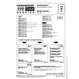
MP-7001SC/7001SM/7001SP/ 7001SS/7001ST
US Model
SERVICE MANUAL
For Technical Service
Ver 1.1 2000. 03 With SUPPLEMENT-1 (9-927-621-82)
SKYTEL
TABLE OF CONTENTS 1. 2. TOOLS .......................................................................... 2 ELECTRICAL ADJUSTMENTS
PD Voltage Adjustment ................................................... 3 Local Frequency Adjustment .......................................... 4 Antenna Adjustment ........................................................ 4 Flexible Circuit Board Repairing � Keep the temperature of the soldering iron around 270 �C during repairing. � Do not touch the soldering iron on the same conductor of the circuit board (within 3 times). � Be careful not to apply force on the conductor when soldering or unsoldering. Notes on chip component replacement � Never reuse a disconnected chip component. � Notice that the minus side of a tantalum capacitor may be damaged by heat.
3.
3-1. 3-2. 3-3. 3-4.
DIAGRAMS
Block Diagram ................................................................ Printed Wiring Boards ..................................................... Schematic Diagram ......................................................... IC Pin Function Description ........................................... 5 8 11 17
4.
ELECTRICAL PARTS LIST ............................... 19
|
|
|
> |
|