|
|
|
Who's Online
There currently are 6043 guests online. |
|
Categories
|
|
Information
|
|
Featured Product
|
|
|
 |
|
|
There are currently no product reviews.
 ;
Doubted for buy this manual as it is my first order here and at not have cover image, I assumed would haven't. However, within 24 hs, already possessed the link to download it. The manual are scanned correctly and have all what is needed. Includes adjustments and diagrams of all circuits. Very satisfied.
 ;
Really good quality, аll readable.! Wonderful work shop. I recommend to all!
;
Good quality service manual.The scheme is on A3 format and very readable.Thank you
;
Very good service-manual with clear electrical diagrams. Thanks you.
;
the manual is in quite good quality and it's in pdf. manual was send in less then 6h.
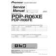
4-16. Rotary Switch, Cam Relay Gear, Change Gear Assembly, Timing Belt
Before replacing the timing belt, remove the guide rail T2 and capstan motor. (Refer to 4-4.)
1. Removal procedure
1) 2) 3) 4) 5) 6) 7) Remove the LS chassis block assembly. (Refer to 4-10.) Remove the guide lock plate (T), pinch pressure assembly and eject arm. (Refer to 4-15.) Remove the cam relay gear 1. Remove the timing belt 2. Remove the HLW cut (0.98 � 3 � 0.25) 3 and change gear assembly 4. Remove the four solderings 5 and remove the FP-299 flexible wiring board 6. Push up the dowel of the rotary switch 7 from the bottom of the mechanism chassis assembly and remove the rotary switch in the direction of the arrow.
2. Attachment procedure
1) Insert the dowel of the rotary switch 7 into the hole on the mechanism chassis assembly and attach the rotary switch clockwise. Align the FP-299 flexible wiring board 6 with the reference hole on the mechanism chassis and solder the flexible wiring board to the rotary switch 7 (at four locations). Attach the change gear assembly 4 with the HLC cut (0.98 � 3 � 0.25)3. Attach the timing belt 2.
Note: There must be a clearance between the rotary switch 7 and timing belt 2.
2)
3) 4) 5)
6) 7) 8)
Attach the cam relay gear 1. The in-phase markings of the rotary switch 7, cam relay gear (2) and cam relay gear (1) must be aligned. Attach the guide lock plate (T), pinch pressure assembly and eject arm. (Refer to 4-15.) Attach the LS chassis block assembly to the mechanical chassis. (Refer to 4-10.) Clean the shaft of the capstan motor. (Refer to 2-2.)
7 Remove the rotary switch in the direction of the arrow.
Attachment direction The ribs must be facing upward. Dowel
Clearance must exist between the claw of the rotary switch and the belt.
1 Cam relay gear (2)
SETTING THE GEAR POSITION
3 HLW cut (0.98 � 3 � 0.25)
Hole of mechanism chassis Rotary switch Cam relay gear (2) Cam relay gear (1)
Belt must be completely free from twist or stain when it is installed
4 Change gear assembly
5 Remove the four solderings
Bend here at right angles.
2 Timing belt
Cam relay gear (1)
6 FP-299 flexible board
Align the holes.
When attaching it, coat the hatched portion with grease.
Fig. 4-16.
� 29 �
|
|
|
> |
|