|
|
|
Who's Online
There currently are 5797 guests online. |
|
Categories
|
|
Information
|
|
Featured Product
|
|
|
 |
|
- SERVICING NOTES
- GENERAL
- DISASSEMBLY
- TEST MODE
- ELECTRICAL ADJUSTMENTS
- DIAGRAMS
- Block Diagram - MD SERVO Section
- Block Diagram - MAIN Section
- Printed Wiring Boards - BD Section
- Schematic Diagram - BD Section
- Schematic Diagram - MAIN Section
- Printed Wiring Board - MAIN Section
- Printed Wiring Boards - MOTOR/SENSOR Section
- Schematic Diagram - MOTOR/SENSOR Section
- Printed Wiring Boards - PANEL Section
- Schematic Diagram - PANEL Section
- IC Pin Function Description
- EXPLODED VIEWS
- ELECTRICAL PARTS LIST
There are currently no product reviews.
 ;
Very Good! All the diagram are easy to read, and its complete.
;
This was an excellent source of detailed assembly information on a device which is at least 12 years old. A very lucky find, coupled with great service.
;
Excellent Service Manual and best price on the Internet. This Service Manual covers everything you could ever need including full circuit schematics, component layout diagrams, stripdown procedure and full parts list/breakdown. I needed this to carry out a modification to one of these headunits and this manual covered everything I needed. Fast delivery, processed within a few hours.
 ;
Thought I would never find a copy of the Technics SX-EN2 Service Manual until I found Owner-Manuals.com. Price was very fair and I received the download promptly. While a photocopy, it is quite readable and includes all the pertinent information and diagrams. Thank you Owner-Manuals!
;
I really like this manual and it's reliable.I found and bought easly.thank you.
8.
FOCUS BIAS ADJUSTMENT
9.
ERROR RATE CHECK
Adjusting Method: 1. Load a continuously recorded disc (Refer to �4. Creating MO Continuously Recorded Disc�) to slot 1. 2. Turn the [      =         SELECTOR       dial and display �CPLAY +         ] MODE�. 3. Press the [ENTER/YES] button and display �CPLAY MID�. 4. Press the [MENU/NO] button when �C = AD = )� is displayed. 5. Turn the [      =         SELECTOR       dial and display �FBIAS +         ] ADJUST�. 6. Press the [ENTER/YES] button and display � / a= �. The first four digits indicate the C1 error rate, the two digits after [/] indicate ADER, and the 2 digits after [a=] indicate the focus bias value. 7. Turn right the [      =         SELECTOR      dial and find the focus +         ]  bias value at which the C1 error rate becomes 220. (Refer to note 2.) 8. Press the [ENTER/YES] button and display � / b= �. 9. Turn left the [      =         SELECTOR       + dial and find the fo        ] cus bias value at which the C1 error rate becomes 220. (Refer to note 2.) 10. Press the [ENTER/YES] button and display � / c= �. 11. Check that the C1 error rate is below 50 and ADER is 00. Then press the [ENTER/YES] button. 12. If the �( )� in � - ( )� is above 20, press the [ENTER/YES] button. If below 20, press the [MENU/NO] button and repeat the adjustment from step 2 again. 13. Press the [REPEAT] button and press the § button to remove the continuously recorded disc.
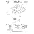
Note 1:The relation between the C1 error and focus bias is as shown in the following figure. Find points a and b in the following figure using the above adjustment. The focal point position c is automatically calculated from points a and b. Note 2:As the C1 error rate changes, perform the adjustment using the average vale.
9-1. CD Error Rate Check Checking Method: 1. Load a test disc TDYS-1 to slot 1. 2. Turn the [      =         SELECTOR       dial and display �CPLAY +         ] MODE�. 3. Press the [ENTER/YES] button and display �CPLAY MID�. 4. �C = AD = )� is displayed. 5. Check that the C1 error is below 20. 6. Press the [MENU/NO] button, stop playback, press the [REPEAT] button, and remove the test disc. 9-2. MO Error Rate Check Checking Method: 1. Load a continuously recorded disc (Refer to �4. Creating MO Continuously Recorded Disc�) to slot 1. 2. Turn the [      =         SELECTOR       dial and display �CPLAY +         ] MODE�. 3. Press the [ENTER/YES] button and display �CPLAY MID�. 4. �C = AD = )� is displayed. 5. If the C1 error is below 50, check that ADER is 00. 6. Press the [MENU/NO] button, stop playback, press the § button, and remove the continuously recorded disc. (To exit from the TEST mode, press the [REPEAT] button.)
11. ADJUSTING POINTS AND CONNECTING POINTS
[BD BOARD] � SIDE A �
CN101
10. FOCUS BIAS CHECK
Change the focus bias and check the focus tolerance amount. Checking Method: 1. Load a continuously recorded disc (Refer to �4. Creating MO Continuously Recorded Disc�.). 2. Turn the [      =         SELECTOR       dial and display �CPLAY +         ] MODE�. 3. Press the [ENTER/YES] button and display �CPLAY MID�. 4. Press the [MENU/NO] button when �C = AD = )� is displayed. 5. Turn the [      =         SELECTOR       dial and display �FBIAS +         ] CHECK�. 6. Press the [ENTER/YES] button and display � �. / c=
D101
[BD BOARD] � SIDE B �
CN107 GND
C1 error 220
The first four digits indicate the C1 error rate, the two digits after [/] indicate ADER, and the 2 digits after [c=] indicate the focus bias value. Check that the C1 error is below 50 and ADER is 02. 7. Press the [ENTER/YES] button and display � / b= �. Check that the C1 error is not below 220 and ADER is not above 02 every time. Focus bias value 8. Press the [ENTER/YES] button and display � / a= (F. BIAS) �. Check that the C1 error is not below 220 and ADER is not above 02 every time. 9. Press the [MENU/NO] button, next press the § button, and remove the continuously recorded disc.
Note 1:If the C1 error and ADER are above 02 at points a or b, the focus bias adjustment may not have been carried out properly. Adjust perform the beginning again.
IC316
b
c
a
IC121 TP68 (FE) TP95 (RF) IC101 TP58 (VC) TP69 (TEO)
TP30 (IOP�)
TP29 (IOP+)
� 17 �
� 18 �
|
|
|
> |
|