|
|
|
Who's Online
There currently are 6036 guests online. |
|
Categories
|
|
Information
|
|
Featured Product
|
|
|
 |
|
|
There are currently no product reviews.
 ;
Good,readable manual. I found other manuals that were not readable when it came to part ID, but the one downloaded from owner-manual.com was better than expected. I will do buisness with owner-manual.com again.
;
Service Manual that I received was very helpful to me. Thank you.
;
The manual is well organized and is easy to read. The chapters are following normal way to proceed.
;
This scanned manual is well done in that most all the pages except for one is straight and clear- the way I would do them. One page was upside down but that happens. For the money that is charged on this site you get a pretty good deal. Now with complex repairs, I still prefer to us paper manuals which I have to buy at stereomanuals but the one I got here was much less than the $45 he was charging but this is a larger than normal manual for three different units. I am a picky manual user because I have used original manuals from Sony and Teac.
;
Very useful service manual, was exactly what i needed.Good quality,reasonable price.Thank you.
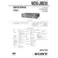
IOP DATA RECORDING AND DISPLAY WHEN OPTICAL PICK-UP AND NON-VOLATILE MEMORY (IC171 OF BD BOARD) ARE REPLACED
The IOP value labeled on the optical pick-up can be recorded in the non-volatile memory. By recording the value, it will eliminate the need to look at the value on the optical pick-up label. When replacing the optical pick-up or non-volatile memory (IC171 of BD board), record the IOP value on the optical pick-up according to the following procedure. Record Procedure: 1. While pressing the [        AMS        ] knob and [  ] button, connect the power plug to the outlet, and release the [        AMS        ] knob â� ± p â� ± and [  ] button. p 2. Turn the [        AMS        ] knob to display â��[Service]â��, and press the [YES] button. â� ± 3. Turn the [        AMS        ] knob to display â��lop Writeâ�� (C28), and press the [YES] button. â� ± 4. The display becomes â��Ref=@@@.@â�� (@ is an arbitrary number) and the numbers which can be changed will blink. 5. Input the IOP value written on the optical pick-up label. To select the number : Turn the [        AMS        ] knob. â� ± To select the digit : Press the [        AMS        ] knob. â� ± 6. When the [YES] button is pressed, the display becomes â��Measu=@@@.@â�� (@ is an arbitrary number). 7. As the adjustment results are recorded for the 6 value. Leave it as it is and press the [YES] button. 8. â��Complete!â�� will be displayed momentarily. The value will be recorded in the non-volatile memory and the display will become â��Iop Writeâ��. 9. Press the [FILTER] button to complete. Display Procedure: 1. While pressing the [        AMS        ] knob and [  ] button, connect the power plug to the outlet, and release the [        AMS        ] knob â� ± p â� ± and [  ] button. p 2. Turn the [        AMS        ] knob to display â��[Service]â��, and press the [YES] button. â� ± 3. Turn the [        AMS        ] knob to display â��lop Readâ�� (C27). â� ± 4. â��@@.@/##.#â�� is displayed and the recorded contents are displayed. @@.@ : indicates the IOP value on the optical pick-up label. ##.# : indicates the IOP value after adjustment 5. To end, press the [        AMS        ] knob or [MENU/NO] button to display â��Iop Readâ��. Then press the [FILTER] button. â� ±
FORCED RESET
The system microprocessor can be reset in the following procedure. Use these procedure when the unit cannot be operated normally due to the overrunning of the microprocessor, etc. Procedure : Disconnect the power plug, short-circuit jumper wire of JW705 and JW706 (RESET). � BAT BOARD (Component Side) �
JW706 JW705
CN703
7
|
|
|
> |
|