|
|
|
Who's Online
There currently are 5967 guests online. |
|
Categories
|
|
Information
|
|
Featured Product
|
|
|
 |
|
|
There are currently no product reviews.
 ;
Well I got all the necessary specifications for the job. Document of good quality and good definition of the diagrams
 ;
hi .full information for JVC GRVF1EG Service Manual its compete .Thank You
;
perfect and good copies, all good readable.
within 24hrs and very cheap also.
;
Great salespeople, muuito attentive recommend everyone buy this site.Obrigado by atendomento..
;
everything was fine - fast, readable, worth the price
3-3. SCREEN (G2)
LAYOUT OF EACH CONTROL
Purity magnet BMC (Hexaploe) magnet V STAT convergence magnet Y-splitting axis correction magnet
SCREEN G2 ADJUSTMENT
1. 2. 3. 4. Input a dot signal from the pattern generator. Set the Picture, Brightness and Colour to minimum. Apply 175V DC from an external power supply to the R, G and B cathodes of the CRT. Whilst watching the picture, adjust [SCREEN G2] located on the FBT [flyback transformer] to the point just before the flyback return lines disappear.
3-4. FOCUS
1. 2. 3 Receive a television broadcast signal. Normalise the picture setting. Adjust the focus control located on the FBT [flyback transformer] to obtain the best focus at the centre of the screen. Bring only the centre area of the screen into focus, the magenta-ring appears on the screen. In this case, adjust the focus to optimize the screen uniformly.
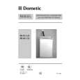
Fig 3-6 Note : If you are unable to adjust the corner convergence properly, this can be corrected with the use of permalloys.
a
b
a-d: screen-corner convergence defect c d
FOCUS
SCREEN (G2)
Permalloy Assy X-4387-214-1
Convergence adjustment with permalloy.
22
|
|
|
> |
|