|
|
|
Who's Online
There currently are 6043 guests online. |
|
Categories
|
|
Information
|
|
Featured Product
|
|
|
 |
|
|
There are currently no product reviews.
 ;
I'm very happy that you all are performing an incredible good job. Furthermore what you did is very useful for all people as me that have electronics as an hobby.Thank you!!!!!
;
Manual found fast and good quality, very helpfull service
;
8-17-12 Been using the sight for about 6 months. Fast Downloads and top quality
Manuels !
 ;
Everything was great, the manual, the response time, the simplicity of the order, and the
Price. The only thing that I could possible say on a negative note would be that the manual I ordered was more for a service tech. There were a lot of schematic diagrams that didn't help me solve the problem. However I would order again and recommend the web sight to others.
;
I'd been looking for this manual for awhile. Exactly what I needed - and at an excellant price. Thanks!
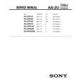
KV-32FV16/32FV26/34FV16/34FV16C/34FX260/34FX260C
2-3. FOCUS
1. Input monoscope signal. 2. Set user controls to normal. 3. Set video mode to STANDARD.
GND
170 + 2.0 Vdc 170Vdc
pedestal
4. Set the PICTURE to maximum. 5. Adjust at 325 Mark for best center/corner focus balance. 6. Receive an entire white signal. Make sure Magenta Ring is at an acceptable level.
2-5. WHITE BALANCE ADJUSTMENTS
NO. 24 25 26 27 28 29 38
Disp. RDRV GDRV BDRV RCUT GCUT BCUT SBRT
Item Red Drive Green Drive Blue Drive Red Cut-off Green Cut-off Blue Cut-off Sub Bright
All Models * 44 38 14:Fix 7 6 6
1. Set program palette to STANDARD and pust RESET.
Focus
2. Input an entire white signal.
Screen (G2)
3. Set to Service Adjustment Mode. 4. Set the PICTURE and BRIGHT to minimum. 5. Adjust with SBRT if necessary.
325 MARK
35 325
6. Set RCUT to "14". 7. Select GCUT and BCUT with 8. Adjust with and and .
35 MARK CENTER CIRCLE
for the best white balance.
9. Set the PICTURE and BRIGHT to maximum. 10. Select GDRV and BDRV with and . then
11. Adjust with 3 and 6 for the best white balance.
2-4. SCREEN (G2)
1. 2. Input dot pattern from the pattern generator. Set the user controls to NORMAL.
12. Write into the memory by pressing .
13. Repeat steps 1-12 for GDR4, BDR4, GCU4 and BCU4 using Video 4 input.
3. Attach the G2-Jig to the C Board. 5. Adjust RCUT, GCUT, BCUT, and SBRT in service mode with an oscilloscope so that voltages on the red, green, and blue cathodes are 170 ± 2.0Vdc. * Use values from Sub Contrast Adjustments NOTE: White balance should be adjusted after Sub Contrast because RDRV is also used in Sub Contrast Adjustment. (See page 22).
5. Observe the screen and adjust SCREEN (G2) VR to obtain the faintly visible background of dot signal. 6. Push the TEST + JUMP (+ Channel) to cut off the signal. The screen should be bright or dark. Brightness of raster must be increased when adjusting. 7. Adjust screen VR until the screen is slightly cut off, or scarcely lights up. A signal cannot be seen when the brightness of the raster is high. 8. Push the JUMP again to release the cut off.
� 13 �
|
|
|
> |
|