|
|
|
Who's Online
There currently are 5865 guests online. |
|
Categories
|
|
Information
|
|
Featured Product
|
|
|
 |
|
|
There are currently no product reviews.
 ;
Up to now you are the BEST! Prompt-efficient and so reasonable ! I have been after SONY service manual for quite some time !Thank you very much ! I can recomend your service to
all my collegagues ! V.Bergfield .
;
This is a very good quality print (scan) of the original SONY service manual. The original from Sony is on very thin paper. Nevertheless it is very clear and sharp and excellent readable. I'm very satisfied to have now this rare document. I've looking for it many years (infrequent). It contains very detailed circuit diagrams, exploded views, part lists, PCB view with good readable connection lines. Very recommended.
;
A complete manual with all the needed details of calibrations and service instructions about the radio receiver.
A big deal.
Many thanks !
;
Fast delivery and good quality copy. To be recommended
;
Excellent product, very clear print. Detailed circuit and assembly diagrams - this enabled me to repair my CD player with confidence. I highly recommend this site.
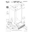
2-7. Picture Tube Removal
10
9
WARNING: BEFORE REMOVING THE ANODE CAP High voltage remains in the CRT even after the power is disconnected. To avoid electric shock, discharge CRT before attempting to remove the anode cap. Short between anode and CRT coated earth ground strap.
8
1 6 7 5
3
Coated Earth Ground Strap
2 4 1. 2. Discharge the anode of the CRT and remove the anode cap. Unplug all interconnecting leads from the Deflection yoke, neck assy, degaussing coils and CRT grounding strap. 3. Remove the C Board from the CRT. 4. Remove the chassis assembly. 5. Loosen the Neck assembly fixing screw and remove. 6. Loosen the Deflection yoke fixing screw and remove. 7. Place the set with the CRT face down on a cushion and remove the Degaussing Coil holders. 8. Remove the Degaussing Coils. 9. Remove the CRT grounding strap and spring tentioners. 10. Unscrew the four CRT fixing screws [ located on each CRT corner ] and remove the CRT. [Take care not to handle the CRT by the neck.] Removal of the Anode-Cap
* REMOVING PROCEDURES.
c
a
b b
Anode button
1 Turn up one side of the rubber cap in the direction indicated by the arrow a
How to handle the Anode-Cap
1. 2. 3. 4.
2 Using a thumb pull up the rubber cap 3 When one side of the rubber cap is firmly in the direction indicated by the separated from the anode button, the arrow b anode-cap can be removed by turning up the rubber cap and pulling it up in the direction of the arrow c
To prevent damaging the surface of the anode-cap do not use sharp materials. Do not apply too great a pressure on the rubber, as this may cause damage to the anode connector. A metal fitting called a shatter hook terminal is fitted inside the rubber cap. Do not turn the rubber foot over excessively, this may cause damage if the shatter hook sticks out.
- 15 -
|
|
|
> |
|