|
|
|
Who's Online
There currently are 5941 guests online. |
|
Categories
|
|
Information
|
|
Featured Product
|
|
|
 |
|
|
There are currently no product reviews.
 ;
I was very glad recieving the service manal from You. Additionaly very fast. Extremaly nice servicing. Thanks very mach! Now my GX-220 working better, than it was made. Alexander from Moscow, Russia/
;
Sweet! I won the item on eBay and couldn't adjust the geometry or even keep a steady picure. This guide has the full schematics (not available anywhere else as far as I could tell), and was a bargain for the wealth of knowledge it contains. I hooked it up to my testing equipment, tweaked a few potentiometers and got it playing videogames in no time. Thanks!
;
It was just what I need to fix my old BMW's CD player. Very convenient also. Thank you.
;
Great Manual! It contains all the wiring schematics and mechanical exploded views that are essential for service and repair. I was surprised I even found this for such an old machine. Only wish I knew of this site many years ago.
;
Great manual very clear copied. You are making an incredible job. I appreciate a lot the rapidity and your efficiency. Thanks a lot
KV-27FV310/29FV310/32FV310/36FV310
2-4. SCREEN (G2)
1. 2. 3. 4. Input dot pattern from the pattern generator. Set the user controls to NORMAL. Attach the G2-Jig to the C Board. Adjust RCUT, GCUT, BCUT, and SBRT in service mode with an oscilloscope so that voltages on the red, green, and blue cathodes are 170 ± 4.0Vdc.
2-5. WHITE BALANCE ADJUSTMENTS
���� ������� ������� ������� ������� ������� ������� ���
1. 2. 3. 4. 5. 6. 7.
��� ����� � � � � � � � ���� ����
���� ��� ����� ���� �����
��� ������ �� �� �� �� �� �� ��
���� ����� ����� ���� ��� ������� ���� ����� ������� ���� ���� ������� ���� ��� ������
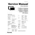
5. Observe the screen and adjust SCREEN (G2) VR to obtain the faintly visible background of dot signal. 6. Push the TEST + JUMP (+ Channel) to cut off the signal. The screen should be bright or dark. Brightness of raster must be increased when adjusting. 7. Adjust screen VR until the screen is slightly cut off, or scarcely lights up. A signal cannot be seen when the brightness of the raster is high. 8. Push the JUMP again to release the cut off. .
170 + 4.0 Vdc 170Vdc
GND
pedestal
Set program palette to STANDARD and push RESET. Input an entire white signal. Set to Service Adjustment Mode. Set the PICTURE and BRIGHT to minimum. Adjust with SBRT if necessary. Set RCUT to �14�. Select GCUT and BCUT with 3 and 5 .
8. Adjust by pressing 1 and 4 for the best white balance. 9. Set the PICTURE and BRIGHT to maximum. 10. Select GDRV and BDRV with and . 11. Adjust with 3 and 6 for the best white balance. 12. Write into the memory by pressing 3 then 5 . 13. Repeat steps 1-12 for GDR4, BDR4, GCU4 and BCU4 using Video 4 input. * Use values from Sub Contrast Adjustments White balance should be adjusted after Sub Contrast because RDRV is also used in Sub Contrast Adjustment. (See page 26)
� 15 �
|
|
|
> |
|