|
|
|
Who's Online
There currently are 5695 guests online. |
|
Categories
|
|
Information
|
|
Featured Product
|
|
|
 |
|
|
There are currently no product reviews.
 ;
The service manual is as described and received the link to the download sooner than expected. Great service, quality product. This site is a big help in the electronics repair business.
;
Il service manual molto accurato. Rapidi nella risposta
;
Quick site processing. A complete and very useful manual with all details. Thank you!
;
Quick service response. A useful and very rare service manual with all details. I recomend this service.
;
I ordered this manual sometime in the afternoon and I received it on my e-mail the same evening.
This is a fantastically good and properly scanned copy of the original manual. All pages are of the same scale and they overlap each other. It means that you can print the manual and easily make it as a convenient paper manual.
The content of the manual is fantastic. Alignment descriptions, PCB layouts and elementary diagrams are explicit and precise. I immediately found what I was looking for. Thanks to this manual and Owner-Manuals.com my amplifier is alive again. Many thanx indded!
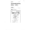
SECTION 3 ELECTRICAL ADJUSTMENTS
FM section Setting BAND switch : FM
FM RF signal generator 0.01µF Set 22.5 kHz frequency deviation by 400 Hz signal Output level : as low as possible
0 dB=1µV
� This adjustment should be executed after MW band adjustment is completed because the LW and SW bands use the BAR ANT and CV1 in common with the MW band. Therefore, if MW band is adjusted, the LW and SW bands must also be readjusted. FM FREQUENCY COVERAGE ADJUSTMENT Adjust for a maximum reading on Level meter. L7 CT1-4 87.3MHz (75MHz) 108.3MHz (109.5MHz)
telescopic antenna input
FM TRACKING ADJUSTMENT Adjust for a maximum reading on Level meter. L6 87.3MHz (75MHz) CT1-3 108.3MHz (109.5MHz)
MW/LW section Setting BAND switch : MW/LW
AM RF signal generator Put the lead-wire antenna close to the set. 30% amplitude modulation by 400 Hz signal Output level : as low as possible
MW FREQUENCY COVERAGE ADJUSTMENT Adjust for a maximum reading on Level meter. L4 520kHz CT1-2 1,650kHz
MW TRACKING ADJUSTMENT Adjust for a maximum reading on Level meter. L1 600kHz CT1-1 1,400kHz
SW section Setting BAND switch : SW1 � SW9
AM RF signal generator 8pF Set 30 % amplitude modulation by 400 Hz signal Output level : as low as possible
AM IF ADJUSTMENT Adjust for a maximum reading on Level meter. T1 455kHz LW FREQUENCY COVERAGE ADJUSTMENT Adjust for a maximum reading on Level meter. L5 CT3 137kHz 295kHz LW TRACKING ADJUSTMENT Adjust for a maximum reading on Level meter. L2 155kHz CT2 260kHz
telescopic antenna input
Level meter 32� Set
Headphones jack (J1)
� Preparation for SW band adjustment After making sure that the MW band adjustment has completed, set the pointer to the center of character of 6.0, 7.2, 11.8 or 21.6MHz which is reference position of dial character, and fix the CV1 at this position. ( ) : Tourist model
� Repeat the procedures in each adjustment several times, and the frequency coverage and tracking adjustments should be finally done by the trimmer capacitors.
�6�
|
|
|
> |
|