|
|
|
Who's Online
There currently are 5930 guests online. |
|
Categories
|
|
Information
|
|
Featured Product
|
|
|
 |
|
|
There are currently no product reviews.
 ;
This manual was very good & was very helpful with repairs.
Always great & fast service from Owner's manual.
;
Very pleased with the quality of the scan. No complaints whatsoever.
 ;
I liked the product. I would use their sevices again.
;
I Recently purchased yet another Service Manual from Owner-Manuals.com, this time for a Sony EVS700ES/UB Videocassette Recorder. The Manual was available for upload within two hours and is an Extremely Good copy, as some of this I was able to enlarge to get even better detail.
Once Again, Very happy with the result!
;
A good and useful manual. With these, We was abled to isolate and pin point the component that was causing the problem. The total time spent in troubleshooting is very much reduced.
CD SECTION
Note: Tracking Balance Adjustment and Tracking Gain Adjustment are done automatically in this set.
Focus Bias Adjustment This adjustment is to be done when the optical block is replaced. Connection:
oscilloscope (AC range) MAIN board TP503 (RF) TP504 (VREF) + �
TEST MODE 1. Press the CD LID OPEN/CLOSE DET switch (S424) on the PUSH SWITCH board. 2. Under standby condition (when the clock appear in the display), short the BP (CD TEST AUTO).
Note: If the power is supplied to the microprocessor once, it is backed up for 3 minutes, therefore the TEST mode will not be activated within 3 minutes even if the power is turned on again. In this case, short instantaneously the BP (CD TEST MANUAL).
3. Press the ^ key, and the focus search is repeated. At this time, check that the optical pick-up objective lens moves smoothly without a sticking or noise. 4. Load the test disc (YEDS-18: Part No. 3-702-101-01), and perform automatic adjustment after the focus search succeded. 5. After automatic adjustment is finished, move the sled motor to the center. At this time, keep pressing the + and = keys to confirm that optical pick-up moves smoothly via most inside track � most outside track � most inside track without a sticking or noise. 6. Confirm the traverse waveform. 7. Press the [WAKE UP TRACK] key. 8. The tracking servo and the sled servo are turned on, the mute is cancelled. 9. Playback the 2nd track. 10. Adjust the RF and jitter waveforms. Connecting points: MAIN Board (See page 13)
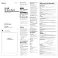
Adjustment Procedure: 1. Connect the oscilloscope to TP504 (VREF) and TP503 (RF) on the MAIN board. 2. Insert the test disc (YEDS-18: Part No.3-702-101-01) and press ^ key to play. 3. Move the optical pick-up to the music area on the disc to enable easy visibility of the eye pattern by + or = key pressing. 4. Adjust RV501 so that the oscilloscope waveform is as shown in the figure below (eye pattern). A good eye pattern means that the diamond shape (�) in the center of the waveform can be clearly distinguished. � RF signal reference waveform (eye pattern)
VOLT/DIV: 0.2 V TIME/DIV: 500 ns 1.3 ± 0.5 Vp-p
When observing the eye pattern, set the oscilloscope for AC range and raise vertical sensitivity.
Adjustment Location: MAIN Board (See page 13)
� 10 �
|
|
|
> |
|