|
|
|
Who's Online
There currently are 6002 guests online. |
|
Categories
|
|
Information
|
|
Featured Product
|
|
|
 |
|
|
There are currently no product reviews.
 ;
This is a very good quality print (scan) of the original SONY service manual. The original from Sony is on very thin paper. Nevertheless it is very clear and sharp and excellent readable. I'm very satisfied to have now this rare document. I've looking for it many years (infrequent). It contains very detailed circuit diagrams, exploded views, part lists, PCB view with good readable connection lines. Very recommended.
;
A complete manual with all the needed details of calibrations and service instructions about the radio receiver.
A big deal.
Many thanks !
;
Fast delivery and good quality copy. To be recommended
;
Excellent product, very clear print. Detailed circuit and assembly diagrams - this enabled me to repair my CD player with confidence. I highly recommend this site.
;
Fast access, 100% correct and complete service manual
SECTION 5 EXPLODED VIEW
r
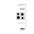
IC BLOCK DIAGRAMS
NF VCC VOL
IC1 TA7358 (ICF-C113V)
REG BIAS
AM OSC GND
BUFFER
AFC DET OUT MIX OUT
MIX
OSC
NOTE : � -XX, -X mean standardized parts, so they may have some difference from the original one. � Color indication of Appearance Parts Example : KNOB, BALANCE (WHITE) ��� (RED) � � Parts color Cabinet's color � Items marked � * �are not stocked since they are seldom required for routine service. Some delay should be anticipated when ordering these items.
8
FM RF IF GND
� The mechanical parts with no reference number in the exploded views are not supplied. � Accessories and packing materials are given in the last of this parts list. � Abbreviation AUS : Australian SW : Swiss
The components identified by mark ! or dotted line with mark ! are critical for safety. Replace only with part number specified.
IF AMP
FM OSC AFC AGC
1
2
3
4
5
6
7
REG OUT AFC AGC
9
4 A : KEY board 4 B : BACK-LIGHT board 4 C : ALARM board 4 D : MAIN board
OSC
OSC OUT
B+
AM RF IN METER
8
FM IF IN FM RF IN
IC2 CXA1019M
4
4A
11
FM/AM FM/AM BAND SELECT GND IN GND
not supplied not supplied
W2
10
28
27
26
25
24
23
22
21
20
19
18
17
16
15
AM IF DET AGC TUNING METER AF POWER AMP AM FE FM IF FM DISCRIMINATOR FM FE
SP1
15 12 16 17
4D
18
T3
W5 W3
6
1 2 3 4 RIPPLE FILTER MIX 5 6 7 8 9 10 11 NC 12 13 14
4B 4C
8
not supplied
LCD1
RF
19 20
ANT1
AF IN
W6
FM DISCRI AF OUT BYP
FE GND AM IF IN
IF OUT
7
5
14
AUS model
21 2 3 9 8 9
14
UK model
14 1 14
AEP, IT, E, SW model US model
The components identified by mark ! or dotted line with mark ! are critical for safety. Replace only with part number specified.
� 17 �
� 18 �
|
|
|
> |
|