|
|
|
Who's Online
There currently are 5762 guests online. |
|
Categories
|
|
Information
|
|
Featured Product
|
|
|
 |
|
|
There are currently no product reviews.
 ;
Superb rendition. Drawings (schematics) complete and unabridged. I do a great deal of vintage audio restoration. Documentation is essential for successful repairs. I have found sources over the years that offer good documentation, but rarely all that is necessary. Owner's Manuals has filled that void with complete and legible documentation. They have narrowed my "favorites" to a more manageable collection. This Denon manual in particular contained the latest revisions level, and offered alterations favorable to updating the item. The Illustrated Parts Breakdown (IPB) was well enough detailed to simplify part symbols and physical locations. You will not be disappointed!
;
Clear and concise. Saved me a lot of time and money.
;
Superb manual. Exactly what I ordered and made available in a very timely manner.
 ;
very fast detailed and accurate hope to do business again
;
This was precisely what I was looking for. Complete and good quality!
ICD-B7
THIS NOTE IS COMMON FOR PRINTED WIRING BOARDS AND SCHEMATIC DIAGRAMS. (In addition to this, the necessary note is printed in each block.) Common Note on Schematic Diagrams: � All capacitors are in µF unless otherwise noted. pF: µµF 50 WV or less are not indicated except for electrolytics and tantalums. All resistors are in � and 1/4 W or less unless otherwise specified. f : internal component. C : panel designation. A : B+ Line. Power voltage is dc 3V and fed with regulated dc power supply from battery terminal.
� Waveforms
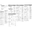
3-7. IC BLOCK DIAGRAMS
1
0.5V/div 0.1µsec/div
1.0Vp-p 4.02MHz
IC103 LM4890MMX
IC101 ta (XOUT)
� � � � �
2
1.0V/div 10µsec/div
SHUTDOWN 1 BIAS 8 VO2 7 GND 6 VDD +IN 3 -IN 4 5 VO1
2.2Vp-p 32.768kHz
BYPASS 2
IC704 1 (32KOUT)
� Voltage and waveforms are dc with respect to ground under no-signal (detuned) conditions. no mark : PB ( ) : REC � Voltages are taken with a VOM (Input impedance 10 M�). Voltage variations may be noted due to normal production tolerances. � Waveforms are taken with a oscilloscope. Voltage variations may be noted due to normal production tolerances. � Circled numbers refer to waveforms. � Signal path. E : PB a : REC
3
0.5V/div 10µsec/div
1.2Vp-p 32.768kHz
IC704 8 (OSCOUT)
4
1.0V/div 0.2µsec/div 3.2Vp-p 5MHz
IC704 RS5C348A-E2
IC703
ul (X2)
Common Note on Printed Wiring Boards: � X : parts extracted from the component side. � Y : parts extracted from the conductor side. � �
f
32KOUT
1
32 kHz OUTPUT CONTROL
: internal component. : Pattern from the side which enables seeing.
COMPARATOR W COMPARATOR
ALARM W REGISTER (WEEK, MIN, HOUR) ALARM D REGISTER (MIN, HOUR)
VDD
Caution: Pattern face side: (SIDE B) Parts face side: (SIDE A) � Lead Layouts
D
10 VDD
Parts on the pattern face side seen from the pattern face are indicated. Parts on the parts face side seen from the parts face are indicated.
SCLK 2 ADDRESS REGISTER SO 3 I/O CONTROL SI 4 SHIFT REGISTER
TIMER COUNTER SEC, MIN, HOUR, WEEK, DAY, MONTH, YEAR
DIV
DIVIDER CORRECTION
9 OSC 8
OSCIN OSCOUT
ADDRESS DECODER
INTERRUPT CONTROL OSC DETECT
Lead layout of conventional IC
VSS 5 VOLTAGE DETECT
7 6
CE INTR
14
14
 $4.99 ICD-B7 SONY
Owner's Manual Complete owner's manual in digital format. The manual will be available for download as PDF file aft…
|
|
|
> |
|