|
|
|
Who's Online
There currently are 5592 guests online. |
|
Categories
|
|
Information
|
|
Featured Product
|
|
|
 |
|
|
There are currently no product reviews.
 ;
Best help everywhere i got from here. My audio medicinman was happy to get this manual from me. So he could repair my pioneer perfectly. Thanks
R O
;
It was very usefull, it is clear the quality is super, the price I paid is very afordable.
Generally speaking Iam very happy with this company.
;
The manual was exactly what I needed, Good quality scans too. superb.
;
I am so happy found this site as it consists of so many Manuls and easy to aquire. This onei s exactly what I wanted and much more as it has info on not only how to use the tuner but how to repair it as well. I will come here 1st before purchasing else where! Thanks owner-manual.com!
;
Top class product, I printed it out on A3 paper and it is clear and very easy to follow.
Cheaper than buying a new radio!
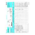
SECTION 4 MECHANICAL ADJUSTMENTS
Precaution 1. Clean the following parts with a denatured alcohol-moistened swab: record/playback head pinch rollers erase head rubber belts capstan idlers 2. Demagnetize the record/playback head with a head demagnetizer. 3. Do not use a magnetized screwdriver for the adjustments. 4. After the adjustments, apply suitable locking compound to the parts adjusted. 5. The adjustments should be performed with the rated power supply voltage unless otherwise noted. Torque Measurement Torque FWD FWD back tension FF/REW Torque meter CQ-102C CQ-102C CQ-201B Meter reading 40 to 70 g � cm (0.56 - 0.97 oz � inch) 1 to 5 g � cm (0.01 - 0.07 oz � inch) 55 to 140 g � cm (0.76 - 1.94 oz � inch)
SECTION 5 ELECTRICAL ADJUSTMENTS
DECK SECTION
1. 2. 3. 4. 5.
0 dB=0.775V
6.
Demagnetize the record/playback head with a head demagnetizer. Do not use a magnetized screwdriver for the adjustments. After the adjustments, apply suitable locking compound to the parts adjusted. The adjustments should be performed with the rated power supply voltage unless otherwise noted. The adjustments should be performed in the order given in this service manual. (As a general rule, playback circuit adjustment should be completed before performing recording circuit adjustment.) The adjustments should be performed for both L-CH and RCH. Tape P-4-A100 WS-48B Signal 10 kHz, �10 dB 3 kHz, 0 dB Used for Azimuth Adjustment Tape Speed Adjustment
Record/Playback Head Azimuth Adjustment (Deck A, Deck B) Note: Perform this adjustments for both decks. Procedure: 1. Mode : Playback
test tape P-4-A100 (10kHz, �10dB) SPEAKER terminal (JK401) set
level meter
2.
Turn the adjustment screw and check output peaks. If the peaks do not match for L-CH and R-CH, turn the adjustment screw so that outputs match within 2 dB of peak.
L-CH peak
output level within 2dB
within 2dB
screw position
R-CH peak L-CH peak R-CH peak screw position
11
|
|
|
> |
|