|
|
|
Who's Online
There currently are 5600 guests online. |
|
Categories
|
|
Information
|
|
Featured Product
|
|
|
 |
|
|
There are currently no product reviews.
 ;
So usefull to make my installation a breeze. 5 stars on quality.
;
very helpful, the information in these manuels are very detailed
;
Please tell us what you think and share your opinions with others. Be sure to focus your comments on the product. You will receive $2.00 of store credit for Your review.
;
Please tell us what you think and share your opinions with others. Be sure to focus your comments on the product. You will receive $2.00 of store credit for Your review.
;
Good copy and great customer service! There was some confusion with my order and it was resolved promptly!
SERVICE NOTE
1. POWER SUPPLY DURING REPAIRS
In this unit, about 5 seconds after power is supplied (8.4V) to the battery terminal using the service power cord (J-6082-223-A), the power is shut off so that the unit cannot operate. This following two methods are available to prevent this. Take note of which to use during repairs.
Battery terminal �
Battery sig terminal
Method 1.
Connect the servicing remote commander RM-95 (J-6082-053-B) to the LANC jack, and set the remote commander switch to the �ADJ� side.
Battery switch
Method 2.
Press the following battery switch using adhesive tape, etc.
Battery terminal �
2.
HOW TO TAKE A CASSETTE OUT WHEN THE MAIN POWER CANNOT BE TURNED ON (FORCED EJECTED)
Procedure: 1. Remove the cassette lid referring to the section �2. DISASSEMBLY, 2-1�. 2. Remove the operation switch block (FK-71 board) referring to the section �2. DISASSEMBLY, 2-5�. 3. Remove the CB-61 board referring to section �2. DISASSEMBLY, 2-4�, and remove the FP-586 flexible board from CN3140 (4P) on the RJ-77 board. 4. Apply +4.5 V from the regulated power supply to the loading motor terminal as shown below and remove the cassette. CAUTION: Be careful not contact with the lid frame assembly when applying +4.5 V.
Control switch block
Regulated power supply
4.5V GND
Lid frame assembly Loading motor
3.
WARNING INDICATORS
If the CAUTION lamp flashes, but no indicators appear on the LCD screen or on the monitor TV screen, it means that an error occurs either in the fan motor or in the fan motor drive circuit. Refer to the schematic diagram on page 4-43 for repair.
�5�
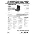 $4.99 GVD900 SONY
Service Manual Complete service manual in digital format (PDF File). Service manuals usually contains circuit diagr…
|
|
|
> |
|